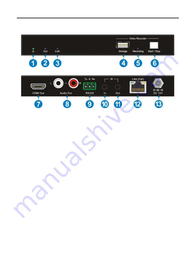
WolfPack HDTVIPH400 User Manual Download Page 9


  POWER LED: 

The LED illuminates green when power is applied. 

  Out LED: 

The LED indicates blue when the HDMI Out port is connected to display 

device. 

  Link LED: 

The LED illuminates blue when there is a valid LAN link between the 

encoder and the decoder. 

  Storage: 

Type-A USB to connect U-disk for video recording. 

  Recording LED: 

The LED indicates blue when recording video. 

  Start/Stop Button: 

Press the button to start or stop video recording. 

  HDMI Out: 

Type-A female HDMI port to connect HDMI display device. 

  Audio Out: 

RCA jack to connect audio output device.


  RS232: 

3-pin terminal block for RS232 routing control. Supports point to point 

unicast and point to multipoint broadcast configuration.


  IR IN:

 3.5mm jack to connect an IR receiver for IR routing control.


IR OUT:

 3.5mm jack to connect an IR emitter for IR routing control. 


LAN (PoE): 

RJ45 port to connect directly to the encoder or a network switch using 

a CATx cable.


DC 12V:

 DC port for AC power adapter connection. 


IP Streaming Encoder and Decoder

3.2 WolfPack HDTVIPH400D Decoder

Summary of Contents for HDTVIPH400

Page 1: ...All Rights Reserved User Manual Version HDTVIPH400_2019V1 0 IP Streaming Encoder and Decoder WolfPack HDTVIPH400...

Page 2: ...rates uses and can radiate radio frequency energy and if not installed and used in accordance with the instructions may cause harmful interference to radio communications It has been tested and found...

Page 3: ...ear water Do not put any heavy items on the extension cable in case of extrusion Do not remove the housing of the device as opening or removing housing may expose you to dangerous voltage or other haz...

Page 4: ...Tab 12 5 3 1 Video Switching 12 5 3 2 Disconnecting Source from RX 13 5 3 3 Preset Management 14 5 3 4 Multiview Setting 15 5 4 Audio Routing Tab 16 5 5 RS232 Routing Tab 17 5 5 1 Assign Encoder to a...

Page 5: ...e Setting 28 5 7 2 2 Video Format Setting 29 5 7 2 3 Factory Reset 30 5 7 2 4 Device Reboot 30 5 7 2 5 Firmware Upgrade 30 5 8 System Management Tab 31 5 8 1 Security Settings 31 5 8 2 System Logs 32...

Page 6: ...owered by IP network Supports video recording The encoder features HDMI loop out Supports audio breakout Supports video matrix and multiview 1 2 Package List IPH400E 1x IPH400E Encoder TX 2x Mounting...

Page 7: ...HDMI HDMI Output Resolution Up to 1080p 60Hz 8bit Audio Output 1 Audio Out L R Audio Output Connector 1 RCA jack Control 1 Storage 1 RS232 1 IR In 1 IR Out 1 LAN PoE Control Connector 1 Type A USB 1 3...

Page 8: ...to connect HDMI video source device HDMI Out Type A female HDMI port to connect HDMI display device RS232 3 pin terminal block for RS232 routing control Supports point to point unicast and point to m...

Page 9: ...r stop video recording HDMI Out Type A female HDMI port to connect HDMI display device Audio Out RCA jack to connect audio output device RS232 3 pin terminal block for RS232 routing control Supports p...

Page 10: ...ed for a switch Distribute full uncompressed data up to 1080p 60Hz resolution and RS232 IR control signals over a single fiber cable Splitter One to Many With only one encoder and one 1G Ethernet swit...

Page 11: ...4 3 System Diagram The following diagram illustrates typical input and output connections that can be utilized with the IP streaming encoder decoder IP Streaming System IP Streaming Encoder and Decode...

Page 12: ...232 devices as needed if you want to test RS232 serial extension between TX and RX units 6 Optional Connect compatible IR emitter modules to the IR output connectors of any TX or RX 7 Optional Connect...

Page 13: ...agement can be used on any Windows PC using Microsoft Net framework 4 0 or later Windows version Before proceeding make sure all IP streaming units are powered ON Then ensure that the IP addresses of...

Page 14: ...e HDMI routing as well as routing of other signals such as analog audio RS232 control etc The default current tab should be Video Switching meaning that the video source displayed by an RX device Deco...

Page 15: ...t the current login account Select Auto Login to save the current login account for auto sign in next time Select Initial Page for system operating easily Set the log save days Select the Follow video...

Page 16: ...tname of the device The default device Hostname is the IPH400E IPH400D Note that the Hostname can be updated at any time The IP Address of the device is also indicated within the tile If a source devi...

Page 17: ...ed active tile using the left mouse button b Hold down the left mouse button and drag the TX tile over the RX tile it is to be joined with Then release the mouse button to drop the TX tile onto the RX...

Page 18: ...e To assign a different input source to a Decoder RX repeat the steps mentioned above dragging a different TX over an RX to associate the decoder itself to the new source device 5 3 2 Disconnecting So...

Page 19: ...delete a stored preset or save the current video switching setting recall a saved preset by selecting preset 1 9 and click the gear icon to select the desired option Rename Clear Preset Save Preset R...

Page 20: ...reens to display All encoders and decoders show on the device list on the right sidebar block Drag and drop the desired encoder decoder unit over the screen block it is to be displayed Click to set fu...

Page 21: ...the desired Encoder TX a Click on the RX and the Encoder TX it is joined to will be highlighted blue b Selecting the respective encoder will highlight all the decoders joined to the same TX 2 If the r...

Page 22: ...the IP Streaming Management interface 2 Verify which Encoders and Decoders are joined together Left click on the device tile you want to see the connection status of All joined together tiles will be...

Page 23: ...outing tab 5 5 2 Sending RS232 Data from IP Streaming Management to a Device 1 Click menu icon of the respective encoder or decoder tile 2 Select Device Options 3 Select Send Receive RS232 4 A dialog...

Page 24: ...P Streaming Management interface 2 Verify which Encoders and Decoders are joined together Left click on the device tile you want to see the connection status of All joined together tiles will be highl...

Page 25: ...spective encoder or decoder tile 2 Select Device Options 3 Select Send Receive IR 4 A dialog box opens 5 Enter the IR string you want to send 6 Click the Send button to send out the string 7 Paired de...

Page 26: ...tring to turn Sony BlueRay player ON and OFF 0000 0067 0000 0015 0060 0018 0030 0018 0018 0018 0030 0018 0018 0018 0030 0018 0018 0018 0018 0018 0018 0018 0030 0018 0018 0018 0030 0018 0030 0018 0018...

Page 27: ...it same with the control PC Firmware Upgrade Update firmware version of decoder Show Info OSD Show the device information of decoder on display Hide Info OSD Hide the device information of decoder on...

Page 28: ...Disable to turn on off the analog audio output of decoder Network Setting Use this tab to modify the device s host name and configure the IP address To rename a device enter a name e g IPH400D 1 into...

Page 29: ...emory and kept until the device is forced back to factory defaults Note Special attention is required when assigning a manual IP address The address has to be both unique and reachable Any mistake whe...

Page 30: ...then click Factory Reset to enter the below interface Click Yes to restore factory default 5 7 1 4 Device Reboot Right click the menu icon of the respective RX tile and click Device Options then clic...

Page 31: ...of the respective RX tile and click Device Options then click Firmware Upgrade to enter the below interface Select upgrade type and click Browse to add the update file and then click Submit to start...

Page 32: ...t of the encoder Factory Reset Restore factory default Reboot Reboot the encoder Update Time Update the device time to let it same with the control PC Firmware Upgrade Update firmware version of encod...

Page 33: ...e is no DHCP server on the network Select Manual to set a static IP address IPV4 address subnet mask and gateway address Press Save to save the new IP address The new IP mode settings are stored in no...

Page 34: ...IR tab to select the IR Code Pattern and Format 5 7 2 2 Video Format Setting To set the video format of encoder right click the menu icon of the respective TX tile and select Video Formats IP Streami...

Page 35: ...con of the respective TX tile and click Device Options then click Reboot to enter the below interface Click Yes to reboot the device 5 7 2 5 Firmware Upgrade Right click the menu icon of the respectiv...

Page 36: ...31 5 8 System Management Tab 5 8 1 Security Settings Select the Security tab in the IP Streaming Management interface to enter the section for modifying the password IP Streaming Encoder and Decoder...

Page 37: ...32 5 8 2 System Logs Select the System Logs tab in the IP Streaming Management interface to enter the section for inquiring the system logs IP Streaming Encoder and Decoder...

Page 38: ...33 5 9 Routing Table The routing table allows to gather info about the video HDMI audio analog audio and RS232 routing status Video Routing Table Audio Routing Table IP Streaming Encoder and Decoder...

Page 39: ...34 RS232 Routing Table IR Routing Table IP Streaming Encoder and Decoder...

Page 40: ...35 6 Panel Drawing IP Streaming Encoder and Decoder HDTVIPH400E HDTVIPH400D...

Page 41: ...ach device has a different IP address in the same LAN Power supply is normal and as specified The connection cables are of high quality and the link has been established successfully 2 If the IP strea...

Page 42: ...ot meeting our specifications No certificate or invoice as the proof of warranty The product model showed on the warranty card does not match with the model of the product for repairing or had been al...

Reviews: