DuoMix Installation Handbook
8
Test the Power Supply
Make sure exposed wires terminals are not in contact with other wires or grounded surfaces. Turn on the power and measure the
voltage between the
Power N — L (15 and 16) terminals using an AC voltmeter, the reading should be between 110 and 130 V (ac).
Test the Powered Inputs
Mixing Demand (
Mix1 Demand & Mix2 Demand)
If a mixing demand is used on the mixing 1 section, measure the voltage between the
Mix1 Demand (1 and 2) terminals. When a call
for heat on the mixing 1 section is present, you should measure between 24 and 240 V (ac) at the terminals. When the demand is
gone, you should measure less than 5 V (ac).
If a mixing demand is used on mixing 2 section, measure the voltage between the
Mix2 Demand (3 and 4) terminals. When a call for
heat on the mixing 2 section is present, you should measure between 24 and 240 V (ac) at the terminals. When the demand is gone,
you should measure less than 5 V (ac).
Test the Outputs
Mixing 1 System Pump (
Mix1 Pmp)
If a mixing system pump is used in the mixing 1 section, make sure power to the terminal block is off and install a jumper between
the
N – Mix1 Pmp (11 and 12) terminals. When power is applied to these terminals, the mixing system pump Mix1 Pmp should start.
If the pump does not turn on, check the wiring between the terminal block and the pump and refer to any installation or
troubleshooting information supplied with the pump. If the pump operates properly, disconnect the power and remove the jumper.
Mixing 2 System Pump (
Mix2 Pmp)
If a mixing system pump is used in the mixing 2 section, make sure power to the terminal block is off and install a jumper between
the
N – Mix2 Pmp ( 7 and 8) terminals. When power is applied to these terminals, the mixing system pump Mix2 Pmp should start.
If the pump does not turn on, check the wiring between the terminal block and the pump and refer to any installation or
troubleshooting information supplied with the pump. If the pump operates properly, disconnect the power and remove the jumper.
Variable Speed Injection Pumps (
Var1 Pmp & Var2 Pmp)
If the variable speed injection pump of the mixing 1 section is used, make sure power to the terminal block is off and install a jumper
between the terminals
N – Var1 Pmp (13 and 14). When power is applied to terminals, the variable speed injection pump should
operate at full speed. If the pump does not operate, check the wiring between the terminal block and the pump and refer to any
installation or troubleshooting information supplied with the pump. If the pump operates properly, disconnect the power and remove
the jumper.
If the variable speed injection pump of the mixing 2 section is used, make sure power to the terminal block is off and install a jumper
between the terminals
N – Var2 Pmp (9 and 10). When power is applied to terminals, the variable speed injection pump should
operate at full speed. If the pump does not operate, check the wiring between the terminal block and the pump and refer to any
installation or troubleshooting information supplied with the pump. If the pump operates properly, disconnect the power and remove
the jumper.
Boiler Enable
If a boiler is connected to the
Boiler Enable (5 and 6) terminals, make sure power to the boiler circuit is off and install a jumper
between the terminals. When the boiler circuit is powered up, the boiler should fire. If the boiler does not turn on, refer to any
installation or troubleshooting information supplied with the boiler and/or Boiler Control. If the boiler operates properly, disconnect
the power and remove the jumper.
Connect the Control
• Make sure all power to the devices and terminal blocks is off and remove any remaining jumpers from the terminals.
• Reconnect the terminal blocks to the control by carefully aligning them with their respective headers on the control and then pushing
the terminal blocks into the headers. The terminal blocks should snap firmly into place.
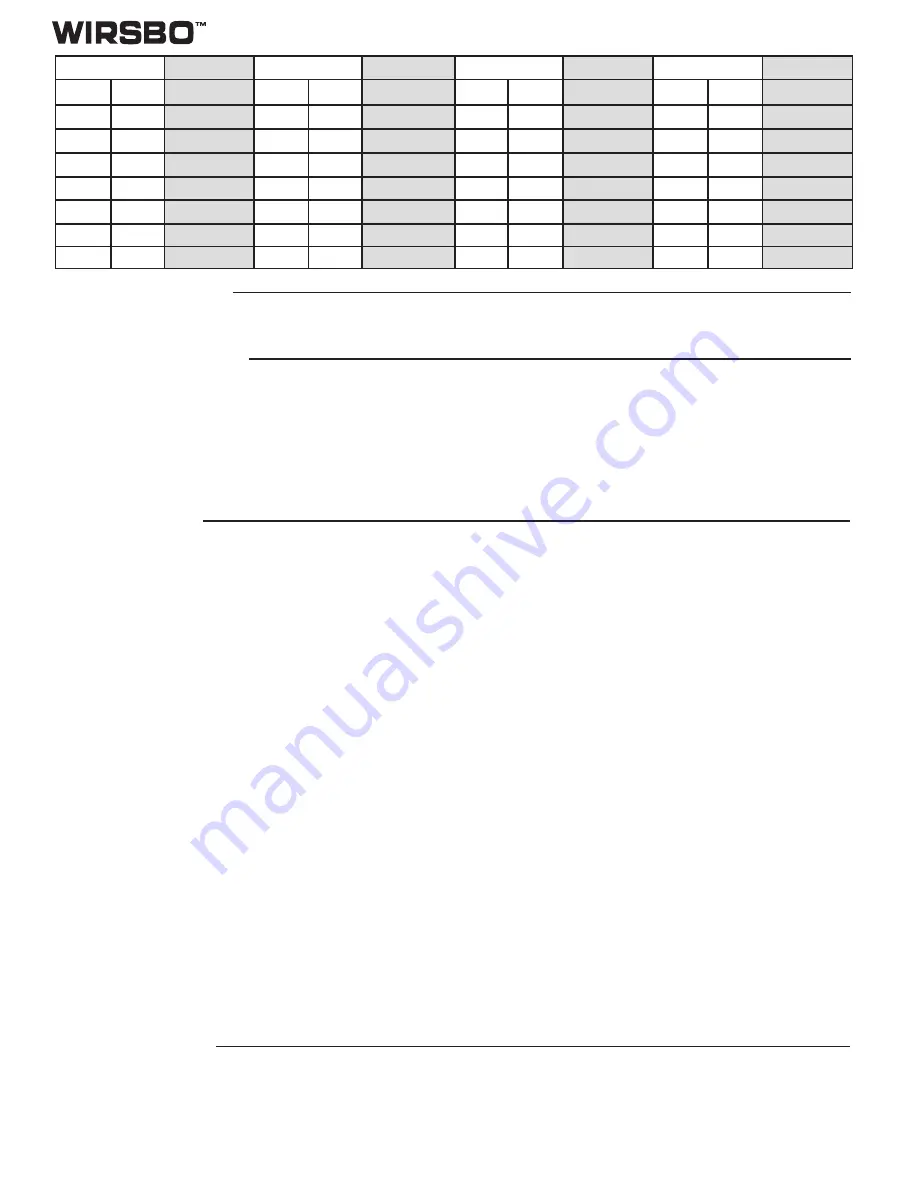
Temperature
Resistance
Temperature
Resistance
Temperature
Resistance
Temperature
Resistance
°
F
°
C
Ω
°
F
°
C
Ω
°
F
°
C
Ω
°
F
°
C
Ω
-50
-46
506,000
20
-7
47,100
90
32
7,400
160
71
1,700
-40
-40
337,000
30
-1
34,400
100
38
5,780
170
77
1,390
-30
-34
228,000
40
4
26,700
110
43
4,730
180
82
1,180
-20
-29
166,000
50
10
19,900
120
49
3,740
190
88
977
-10
-23
116,000
60
16
15,000
130
54
3,100
200
93
838
0
-18
86,500
70
21
11,900
140
60
2,490
210
99
701
10
-12
61,700
80
27
9,170
150
66
2,010
220
104
606
Summary of Contents for DuoMix 201
Page 17: ......
Page 18: ...Display Menu Cont...
Page 22: ...DuoMix Installation Handbook 22...
Page 23: ...DuoMix Installation Handbook 23...
Page 24: ...DuoMix Installation Handbook 24...
Page 25: ...DuoMix Installation Handbook 25...
Page 30: ...DuoMix Installation Handbook 30...


