background image

10 Engineering

WirelessHART Fieldgate SWG70

64

Hauser

10.2.2 Input Status

Input Status allows the Modbus mapping of a device with single or multiple binary output. As 
Fieldgate SWG70 supports extended registers, values are normally assigned to the registers with the 
reference addresses 100001 to 165536. The reference addresses are obtained by adding the register 
number to 100,000. The dialogue checks for completeness of entries (line turns red if not correctly 
filled out) as well as double assignment to the registers (line turns yellow).

The algorithm assumes that the discrete device delivers a maximum of 256 packed discrete values, 
each of comprising 16 bits of an unsigned Integer16 (UINT16). Each bit represents a unique input 
status. Fieldgate SWG70 first splits the data into two bytes and reserves 8 registers for each byte, 
i.e. one for each bit contained.

•  Least significant byte (Bits 0 - 7) maps e.g. to registers 100001 - 100008
•  Most significant byte (Bits 8 - 15) maps e.g. to registers 100009 - 100016

The value entered after the byte selection determines which of the packed discrete values is to be 
mapped, e.g. 0 will map the first set of packed discrete values and 15 the sixteenth set of packed 
discrete values. More information is to be found in Appendix A.2.2.

NOTE!

• Some HART devices map their discrete value and status as PV in HART CMD 3. In this case the 

value and status information will be found in the appropriate Input or Holding Register, 
see Chapter 10.2.3.

• If a device status is mapped as a UINT8 to the Input Status registers, the status will be found in 

only one of the bit registers, e.g. in Bit 0. The UINT8 is stored as a 16-bit value, the MSB being 
filled with "0"s, see Chapter A.1.3.

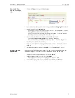
1 Click on the 

Engineering =>Modbus Mapping =>Input Status 

leaf to display the 

associated parameters:

2 Click on 

Generate

 to open the Generate tab

The significance of the parameters is described in the table overleaf

Summary of Contents for Fieldgate SWG70

Page 1: ...BA00064S 04 en 13 13 Version 1 01 xx 71213937 Operating Instructions WirelessHART Fieldgate SWG70 Intelligent WirelessHART gateway with Ethernet and RS 485 interfaces ...

Page 2: ......

Page 3: ...tion 20 5 1 Connections and interfaces 20 5 2 Connecting to power supply and grounding 21 5 3 Connecting to Ethernet 22 5 4 Connecting to RS 485 23 5 5 Cable glands and housing cover 24 6 Operation 25 6 1 Operating and display elements 25 6 1 1 LEDs 26 6 1 2 Buttons 27 6 1 3 DIP switches 28 7 Commissioning 29 7 1 Preliminaries 29 7 1 1 Software package 29 7 1 2 Setup 29 7 2 Ethernet connection 30 ...

Page 4: ...by Fieldgate LEDS 84 14 2 2 Wired Communication Faults 84 14 2 3 Wireless Communication Faults 85 15 Technical Data 86 15 1 Input 86 15 2 Output 86 15 2 1 Ethernet 100 BASE T 100 BASE TX 86 15 2 2 RS 485 serial interface 86 15 3 Power Supply 87 15 4 Environment 87 15 5 Mechanical Construction 88 15 6 Operability 89 15 7 Certificates and Approvals 89 A Appendix Modbus Interface 90 A 1 Introduction ...

Page 5: ...de mark of the Adobe Systems Incorporated All other brand and product names are trademarks or registered trademarks of the companies and organisations in question Package version Manual Changes Remarks 1 00 xx BA064S 04 en 06 10 Original manual 1 01 xx BA00064S 04 en 13 13 New Functions Navigation changed see Chapter 7 6 Channel Blacklisting possible Chapter 8 2 2 Topology with signal strength Cha...

Page 6: ...rews of the housing housing cover must have been tightened with the appropriate torque Only cable of the appropriate size must be used in the cable glands All cable glands must have been tightened with the appropriate torque see Chapter 5 5 All empty cable glands must have been sealed with sealing plugs Once a Fieldgate SWG70 has been used in a non Ex installation it should never be used in an Ex ...

Page 7: ... Compliance Statement Conditions of Compliance R TTE This device complies with the requirements of the EC Telecommunications Directive 1999 5 EC ETSI EN 300 328 V1 7 1 2006 10 ETSI EN 301 489 17 V1 2 1 2002 08 EN 60950 2001 FCC This device complies with CFR 47 Part 15 of the FCC Rules Operation is subject to the following two conditions 1 This device may not cause harmful interference and 2 this d...

Page 8: ...specifications in the certificate or in a safe area Explosion hazardous area Symbol used in drawings to indicate explosion hazardous areas Devices located in and wiring entering areas with the designation explosion hazardous areas must conform with the stated type of protection Safe area non explosion hazardous area Symbol used in drawings to indicate if necessary non explosion hazardous areas Dev...

Page 9: ...of damage to the Fieldgate contact your Endress Hauser Sales Center see Chapter 13 1 2 Where possible return the fieldgate to us in its original packing 2 1 2 Scope of delivery Please check that the delivery is complete and free of defects before starting installation The scope of delivery comprises the following parts WirelessHART Fieldgate SWG70 Antenna Short instructions and CD ROM Depending up...

Page 10: ...folder System Requirements on the Product CD ROM The full licensing agreement is also to be found on the CD ROM The software required for start up and commissioning i e the Internet browser is either freely available or is subject to the licensing conditions of its manufacturer Installation of this software on your computer implies that you accept the terms of the corresponding licensing agreement...

Page 11: ... Band IEEE 802 15 4 wireless network as physical layer The WirelessHART devices form a mesh network in which every device is not just a measurement point but also a repeater This results in a wider range for the whole network as well as increased reliability through redundant communication paths The network may comprise three types of device WirelessHART gateway Fieldgate SWG70 WirelessHART field ...

Page 12: ...k keys as well as scheduling and routing information to the field device The field device is told how to participate in the network and receives various information from the WirelessHART gateway Number and identity of neighbouring WirelessHART field devices When to send messages and which channels to use When to repeat messages for other WirelessHART field devices The optimal communication path fo...

Page 13: ...strument list First in First Out principle Within an I O card the WirelessHART device itself as well as status information is assigned to Channel 0 If the WirelessHART device is an adapter all field devices connected to it are assigned to channel 1 multi drop mode The list of the connected field devices is also called sub device list Fig 3 3 Instrument list If a WirelessHART device loses communica...

Page 14: ...nt immediately provided that the response is available in the cache Long Tag Emulation WirelessHART uses the long tag for addressing devices Not every HART device supports long tags for example older HART devices with HART Protocol Version 5 or less do not support long tag addressing If a HART 5 0 device is connected to a WirelessHART adapter the WirelessHART gateway emulates the long tag using th...

Page 15: ... is 200 m In this case install wireless devices at least 3m above the ground or the floor Consider moving objects that could affect the device s antenna range Make sure that the device s antenna is aligned vertically If possible position the Fieldgate at or near the centre of the network it should be in contact with at least 20 of the devices in the network Do not position WirelessHART devices dir...

Page 16: ...allation WirelessHART Fieldgate SWG70 14 Endress Hauser 4 1 3 Antenna characteristics Fig 4 1 shows the antenna gain in the vertical and horizontal planes Fig 4 1 Antenna gain in the vertical above and horizontal planes ...

Page 17: ...er is in the horizontal plane decreasing to 50 at an angle of 39 Almost no signal will be radiated directly above and below the antenna Consider this when planning a WirelessHART network The height differences between wireless devices in a network should not be too large The schematic is valid only for an antenna placed outdoors with no metal surfaces near The radiation pattern changes significant...

Page 18: ...positioning is good when the network participants are within the antenna range Fig 4 3 Example of good positioning The positioning is poor when neighbours are not in the antenna range or within the weaker signal zone of the antenna Fig 4 4 Example of poor positioning PWR COM FLT height distance PWR COM FLT height distance ...

Page 19: ...th a remote antenna installed in an explosion hazardous area then the antenna must possess the appropriate Ex certification NOTE The use of a remote antenna of a different type or that operates at a higher gain than specified in the requirements below is subject to legal restrictions Only remote antennas that conform with the following requirements may be connected to the Fieldgate The antenna mus...

Page 20: ...arrestor must be installed directly on the Fieldgate SWA70 antenna connection Install the components according to Fig 4 6 Fig 4 6 Installation of an remote antenna 1 Before installing the remote antenna make sure that the Fieldgate has been disconnected from line power 2 Install the components according to Fig 4 6 3 Install the surge arrestor in a way that all indoor connections are protected 4 Co...

Page 21: ...s Choose a mounting location that meets the climatic limits specified and radio requirements in the technical data The housing has a degree of protection of IP65 and is designed for wall mounting mounting accessories not included Required tools 2 screws M6 Drill Screwdriver Fig 4 7 Mounting holes and housing screws Mounting the Gateway 1 Drill 2 holes in the mounting surface so that they match the...

Page 22: ...ettings by software see Chapter 8 Warning When Fieldgate SWG70 is installed in Ex Ex Zone 2 the connection disconnection of cables is permitted only in the absence of any potentially explosive atmosphere or when the fieldgate is not connected to the power supply Fig 5 1 Connections and interfaces 1 Grounding terminal 5 Antenna 2 RS 485 interfaces duplicated terminal block for daisy chain capabilit...

Page 23: ...cover 3 Route the 24 VDC power cable through the second cable gland from right The permissible cable diameter lies between 6 mm and 10 mm 4 Connect the 24 VDC power cable to the first power supply connection Line 1 observing polarity see Fig 5 1 above 5 If you want to connect a redundant power supply optional route the second 24 VDC power cable through the cable gland on the far right of the housi...

Page 24: ...through cable is used in connection with a hub switch or router The other end of the cable is fitted with a standard RJ 45 connector Connecting to Ethernet Network 1 Check that the power is switched off 2 If applicable unscrew the four screws of the housing cover see Fig 4 5 in Chapter 4 2 and remove the housing cover 3 Route the Ethernet cable through the cable gland in the middle of the gateway ...

Page 25: ... the cables Fig 5 4 RS 485 interface Connecting to RS 485 1 Check that the power is switched off 2 If applicable unscrew the four screws of the housing cover see Fig 4 5 in Chapter 4 2 and remove the housing cover 3 Route the RS 485 cable through the first cable gland from left The permissible cable diameter lies between 6 mm and 10 mm 4 Connect the RS 485 cable to the left terminal block labelled...

Page 26: ...le glands must be tightened with the appropriate torque all seals must be undamaged and fitted correctly all empty cable glands must be sealed with appropriate plugs The tightening torques of cable glands depend on what type of cable is used and must therefore be determined by the user The cap nuts must be securely tightened Tightening the cap nuts too tight can have a negative effect on the prote...

Page 27: ...e SWG70 is installed in Ex Zone 2 and the power is switched on the operation of DIP switches and buttons as well as the connection disconnection of cables is permitted only in the absence of any potentially explosive atmosphere The operation of DIP switches and the connection disconnection of cables in Ex Zone 2 is permitted however when the power to Fieldgate SWG70 is switched off Fig 6 1 Operati...

Page 28: ...s Significance On OK Fieldgate SWG70 is powered up and running Flashes Not ready On power up indicates that the Fieldgate application is running but the Fieldgate is not yet ready to answer HART commands Off No power The power supply is not connected Fieldgate is not ready Mode Status Significance Flashes Flashes shortly whenever a valid WirelessHART message is received by the Gateway on the Wirel...

Page 29: ...pprox 3 seconds all LEDs light up to confirm the reset Button P2 Communication reset Press the button for more than 3 seconds All Fieldgate SWG7 configuration parameters related to the wired communication channels are reset to factory settings After approx 3 seconds all LEDs light up to confirm the reset Button P1 P2 DIP Switch 8 OFF Password reset Press buttons P1 and P2 simultaneously for more t...

Page 30: ... Switches 1 4 Polling address 3 Switch 7 RS 485 termination 2 Switches 5 6 Baudrate 4 Switch 8 Security mode 24V 24V 0V 0V LINE1 LINE2 A B SHD RS485 T1 T2 RX RX TX TX ON OFF SHD A B SHD RS485 ETHERNET 1 2 3 4 ON OFF 1 2 3 4 5 6 7 8 Switch Function SW1 SW2 SW3 SW4 Value SW1 SW2 SW3 SW4 Value SW1 SW4 Bus address 1 OFF OFF OFF OFF 0 OFF OFF OFF ON 8 ON OFF OFF OFF 1 ON OFF OFF ON 9 OFF ON OFF OFF 2 O...

Page 31: ... Server which can be used to set up and monitor both the device and the network The structure of the parameter blocks and parameters is identical with that of the Fieldgate SWG70 DTM Connection to the Web Server is made by an Internet browser e g Windows Explorer To connect to and set up via Web Server follow the preliminary procedures in Chapter 7 2 FieldCare Setup via FieldCare differs from the ...

Page 32: ...er Windows systems consult your system administrator Fieldgate SWG70 is delivered with the default IP address 192 168 1 1 In order that the host computer can communicate with the Fieldgate Web Server Check that the computer can reach the Fieldgate via ports 80 443 502 and 5094 If you are not sure how to do this consult your network administrator For the initial commissioning set your computer s ad...

Page 33: ...ddress of Fieldgate SWG70 192 168 1 1 and press Enter 2 Accept the site certificate in the dialog which now appears 3 Now the Login of the Web page appears To open the Fieldgate SWG70 Web pages Enter User name default admin and Password default admin and press OK 4 If you are not able to connect to the Fieldgate Ping the Fieldgate using the Command prompt Check that any proxy server is switched of...

Page 34: ...verter or the RS 485 USB converter to your PC 2 In the case of the RS 485 USB converter install any driver that is delivered with the device 3 To find out to which COM port the converter is connected open the Windows device manage e g for Windows XP Start Settings Control Panel System Hardware Device Manager 4 Under Ports COM LPT you should see the converter and the COM port assigned to it 5 Note ...

Page 35: ...continue If you do not accept the licence agreement the wizard closes 4 In the Customer Information dialog enter details of the user then press Next to continue 5 In the Choose Setup Type dialog select Complete If the wizard has found an earlier version of the DTM press Upgrade 6 DTM Setup Wizard now locates the FieldCare HART DTM folder and displays it in the Ready to Install dialog press Install...

Page 36: ...t Up Screen dialog press Continue and in the FieldCare dialog press Open An empty Project workspace appears 3 Right click on the DTM Catalog menu and select Update The Update DTM Catalog dialog appears Press Update to start the search for new DTMs make take several minutes 4 When the search is complete the new DTM will be shown in the left hand pane Select the Wireless Fieldgate and HART IP DTMs a...

Page 37: ...nect to FieldCare via the RS 485 interface the HART Communication CommDTM must be added and configured instead of the HART IP CommDTM The procedure is similar to that described here whereby the configuration involves other parameters such as selection of multiplexer option COM port and baudrate 1 In the FieldCare project workspace right click on the Host node and select Add Device 2 The Add New De...

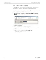
Page 38: ...ialog closes and the Fieldgate SWG70 DTM is added below the HART IP node 4 If the factory IP address 192 168 1 1 or Ethernet Port 5094 of the Fieldgate SWG70 has been changed right click on the HART IP Communication node and select Additional Functions Set DTM Addresses The Set DTM Addresses Dialog opens 5 Enter the new IP address and or Ethernet UDP Port number and press Update Changed Data 6 Clo...

Page 39: ...arrows turn green 2 Right click on the Fieldgate SWG70 node and select Connect The Fieldgate SWG70 DTM is put on line and the two arrows turn green 3 Right click on the Fieldgate SWG70 node and select Online Parameterize The DTM of Fieldgate SWG70 opens 4 Expand the navigation tree to reveal the parameter blocks here shown with the Identification page open You are now ready to configure the device...

Page 40: ...line and the two arrows turn green 2 The Fieldgate CommDTM now scans the wireless network and automatically adds all WirelessHART devices found to the network in our case the SWA70 adapters Note If no device is found although communication has been established check that the adapters have been configured with the correct network identification and join key It may take up to ten minutes for a wirel...

Page 41: ...d select Create Network You can also click on the Create Network icon to do this The adapter is put on line and the two arrows turn green 3 The adapter DTM now scans the wired interface and automatically adds all HART devices found to the network Depending upon FieldCare configuration and number of devices this may occur automatically or after confirmation with OK in the Scanning Result dialog Dep...

Page 42: ...ers DTM dialog Online Parameterization Chapter 8 Identification Chapter 8 1 Wireless Communication Chapter 8 2 Setup Basic Advanced Chapter 8 2 1 2 Operating modes Chapter 8 2 3 Wired Communication Chapter 8 3 Interfaces Serial Chapter 8 3 1 Ethernet Chapter 8 3 2 Protocols HART Chapter 8 3 3 Modbus Chapter 8 3 4 AMS Chapter 8 3 5 Diagnosis DTM dialog Diagnostics Chapter 9 Identification Chapter 9...

Page 43: ...g Example Default Device Long Tag Identifies Fieldgate within the plant network Max 32 character ASCII Latin 1 string Fieldgate_ SWG70_01 Device Tag Identifies Fieldgate within the plant network Max 8 character HART Packed ASCII string FG_100 Descriptor User text describing e g function or location of Fieldgate SWG70 Max 16 character HART Packed ASCII string AREA1 TANKS Date Date dd mm yyyy indica...

Page 44: ...of 4 User network password 8 hexadecimal characters Part 3 of 4 33333333 2B204861 Join Key Part 4 of 4 User network password 8 hexadecimal characters Part 4 of 4 33333333 75736572 Write Join Information Press the button to download your changes and restart the network RTC Date Indicates date setting for the network RTC Time Indicates time setting for the network Network start date Indicates the da...

Page 45: ...Functions Reset see Chapter 11 1 7 The wireless network is now up and running Bandwidth Profile This option allows you to increase network performance by reducing network latency If battery power is being used this option increases energy consumption and reduces battery life If a faster response time is more important than battery life set the profile to medium or high To activate the new profile ...

Page 46: ... If a WirelessHART network is to be run parallel to a IEEE 802 11 network several WirelessHART channels must be disabled Also note that the channel numbering differs for each type of network For example If the WLAN uses channel number 5 channels 5 to 8 in the WirelessHART network must be disabled Disabling channels 1 Disable a channel by deactivating its check box in the Channel Blacklist The numb...

Page 47: ... Type Displays the device type as registered at the HART Communication Foundation Status Displays the communication status Connected Flashing Device connected being identified Continuous Device connected but not identified Communication failure Dev Status Displays the device status Good Out of specification Failure Note that the device status that is displayed in the list may differ from the actua...

Page 48: ... the interface protocol parameters in the appropriate Protocol leaf see Chapters 8 3 3 and 8 3 4 Modbus serial allows access for one master HART serial allows access for one primary master and one secondary master Serial parameters Parameter Meaning Example Default Terminal Resistor Selection Specifies whether hardware DIP switch 6 or software termination settings are to be used DIP Switch Softwar...

Page 49: ...g Example Default IP Address Assignment DHCP DNS Specifies whether Fieldgate SWG70 IP network and DNS address is to be assigned manually or automatically Manually The settings in the dialogue are used Automatically The IP address of the DNS is assigned by a DHCP server Manually Manually IP Address Sets fixed fieldgate IP network address for manual assignment mode 192 168 1 1 192 168 1 1 Netmask Se...

Page 50: ...her hardware DIP switch 0 3 or software bus address settings are to be used DIP Switch 0 15 Software 0 63 Software Software Bus Address Sets the HART address of the wireless fieldgate when Bus Address Selection is set to Software When DIP Switch is selected displays the setting 63 1 Baud Rate Selection Specifies whether hardware DIP switch 4 5 or software baudrate settings are to be used DIP Switc...

Page 51: ... address of the wireless fieldgate when Bus Address Selection is set to Software When DIP Switch is selected displays the setting 63 1 Baud Rate Selection Specifies whether hardware DIP switch 4 5 or software baudrate settings are to be used DIP Switch Setting 9600 Bit s 57600 Bit s Software Setting 1200 Bit s 115200 Bit s Software Software Baud Rate Sets the baudrate of the wireless fieldgate whe...

Page 52: ...set in this leaf 1 Click on the Wired Communication Protocols AMS to display the associated parameter The significance of the parameters can be taken from the table whereby mandatory parameters are highlighted by bold type AMS Ethernet Port Parameter Meaning Example Default Port Number Ethernet Sets Fieldgate SWG70 port number for AMS integration AMS XML allows access for one primary master and on...

Page 53: ...within the plant network Device Tag Identifies Fieldgate within the plant network Descriptor User text describing e g function or location of Fieldgate Date Indicates a date Message User message transmitted with information from Fieldgate SWG70 Universal Command Revision Revision of the HART protocol supported by Fieldgate SWG70 Device Revision HART Revision of device specific commands supported b...

Page 54: ...connected to a specific channel Number of Devices Indicates the current number of subdevices Every device counts as a subdevice no matter if it is a wireless device or a wired device connected to a WirelessHART adapter Lifetime Network Statistics Reliability Ratio of the number of successful packet transmissions to the sum of the successful and permanently lost packet transmissions taken across th...

Page 55: ...es HART 6 0 IO card Identifier of fieldgate card used by the device Channel Identifier of card channel used by the device Device Type Designation of connected device Status Communication status of the associated device Connected Flashing Device connected being identified Continuous Device connected but not identified Communication failure Dev Status Device status of the associated device Good Out ...

Page 56: ...ice Long Tag Long Tag of connected device IO card Identifier of fieldgate card used by the device Channel Identifier of card channel used by the device Device Type Designation of connected device Status Communication status of the associated device Connected Flashing Device connected being identified Continuous Device connected but not identified Communication failure Dev Status Device status of t...

Page 57: ...uality respectively traffic for each connection path The significance of the colours line thicknesses and other functions are to be found in the table which follows 2 In the example above The most traffic flows between the Adapter WAD_301 and Fieldgate SWG70_01 Less traffic flows between Adapter WAD_302 and WAD_303 respectively and Fieldgate SWG70_01 as well as between Adapter WAD_302 and WAD 303 ...

Page 58: ...aximum possible Lawn Green Signal stability 70 80 of maximum possible Bright Green Signal stability 80 90 of maximum possible Green Signal stability 90 100 of maximum possible Controls Reset Zoom Resets the zoom to show everything Refresh Updates the information on signal quality and traffic Zoom rider Increases or decreases the magnification of the topology view Horizontal image origin Indicates ...

Page 59: ... in the table below Overview parameters Parameter Meaning Messages received through HOST Total number of messages received from the host since the start up or last reset of Fieldgate SWG70 Messages returned to HOST Total number of messages returned to the host since the start up or last reset of Fieldgate SWG70 Number of requests forwarded to IO system Total number of messages from the host forwar...

Page 60: ... indicates whether the described condition is currently valid 1 Click on the Diagnostics Wired Communication HART leaf to open the list The significance of the parameters is described in the table which follows In the case of the Cumulative Extended Device Status the user must turn to the Wireless Communication Details list to get more information on individual device status see Chapter 9 2 2 ...

Page 61: ...tus Primary Variable Out of Limits PV of a device in the network is out of limits Non Primary Variable Out of Limits SV TV QV of a device in the network is out of limits Loop Current Saturated Loop current of a a device in the network above 20 mA Loop Current Fixed Loop current of a a device in the network is fixed to 4 mA multidrop mode More Status Available Device in the network has more status ...

Page 62: ...ial number that is assigned at manufacturing time and that differs for each HART device of a given type Extended Device Type Code Unique code identifying the HART product family Delete button Deletes a device from the instrument list Press Apply to register the change in Fieldgate SWG70 If the device is still communicating with the network it will automatically reappear in the list at the next ref...

Page 63: ...ck into the last row of the instrument list and enter the Long Tag of the device 3 Enter the following optional additional parameters by clicking on the appropriate field I O Card to which the device should be attached Channel adapters are assigned to Channel 0 devices to Channel 1 Device ID unique HART serial number assigned on manufacture of the device Extended Device Type Code unique code ident...

Page 64: ...Instrument List to display the empty instrument list You may have to enable the Engineering menu first 5 Press Import Project Tree to import the network tree 6 Press Export CSV to store the instrument list on your computer 7 Close the Offline Parameterize dialogue and open the Online Parameterize dialog Select Engineering Instrument List to display the empty instrument list 8 Press Import CSV and ...

Page 65: ...swap option for Modbus data transmission see also Appendix A 1 3 Big Endian no swap Register 0 Register 1 Source bytes 0xABCD 0xEFGH Target bytes 0xABCD 0xEFGH Little Endian Register swap Register 0 Register 1 Source bytes 0xABCD 0xEFGH Target bytes 0xEFGH 0xABCD The Swap Option does not apply to the Input Status registers Big Endian Big Endian Addressing Method Selects whether the mapping is to b...

Page 66: ...it contained Least significant byte Bits 0 7 maps e g to registers 100001 100008 Most significant byte Bits 8 15 maps e g to registers 100009 100016 The value entered after the byte selection determines which of the packed discrete values is to be mapped e g 0 will map the first set of packed discrete values and 15 the sixteenth set of packed discrete values More information is to be found in Appe...

Page 67: ...gital I O device For Input Status this is normally 1 1 1 Generation Order Order in which the devices are mapped to the Modbus registers Index According to the index number see Instrument List Chapter 10 1 for example Alphabetical In alphabetical order according to the Long Tag Alphabetical sub device In alphabetical order according to the Long Tag of the sub device IO card channel According to the...

Page 68: ...st Significant Byte will map Bits 8 15 of an UINT16 5 Enter a the index of the UINT16 to be mapped 0 to 255 into the value field which now opens 6 Repeat Steps 4 and 5 for all UINT16s 7 If required check the Delete all Mappings checkbox to overwrite any existing mappings If the box is unchecked any new devices found will be added an existing table 8 Click Generate to write the mapping to the table...

Page 69: ...e device in the Value column Least Significant Byte will map Bits 0 7 of an UINT16 Most Significant Byte will map Bits 8 15 of an UINT16 5 Enter a the index of the UINT16 to be mapped 0 to 255 into the value field which now opens 6 Repeat Steps 2 4 and 5 for all other devices 7 If required manually edit the mapping table by deleting unwanted entries with the delete button 8 After the mapping table...

Page 70: ...to the Holding Registers with the reference addresses 400001 to 465536 see Read Modbus Registers Mode in Chapter 10 2 1 The reference addresses are obtained by adding the register number to 300 000 or 400 000 respectively The dialogue checks for completeness of entries line turns red if not correctly filled out as well as double assignment to the registers 1 Click on the Engineering Modbus Mapping...

Page 71: ...s this is normally 1 depending on the Modbus system in use 13 1 Generation Order Order in which the devices are mapped to the Modbus registers Index According to the index number see Instrument List Chapter 10 1 for example Alphabetical In alphabetical order according to the Long Tag Alphabetical sub device In alphabetical order according to the Long Tag of the sub device IO card channel According...

Page 72: ...st Alternatively click in the value field and choose the values you require Note that the list will be replicated for all devices so some editing may be required later 5 If required check the Delete all Mappings checkbox to overwrite any existing mappings If the box is unchecked any new devices found will be added to an existing table 6 Click Generate to write the mapping to the table on the Table...

Page 73: ... If you select CMD 48 Device Status enter a response byte as well For more information see CMD48 Read Additional Status Information Chapter A 3 3 5 Repeat Steps 2 4 and 5 for all other devices 6 If required manually edit the mapping table by deleting unwanted entries with the delete button 7 After the mapping table is complete click Apply to store the it in Fieldgate SWG70 Import and Export of map...

Page 74: ...View parameters Parameter Meaning Select Map Uploads a map in jpg format Reset Zoom Resets the zoom to the minimum value Import Uploads the current devices and positions from a CSV file Export Stores the current devices and positions in a CSV file Refresh Updates the information on signal quality and traffic Zoom rider Increases or decreases the magnification of the topology view Horizontal image ...

Page 75: ... Map to select a background image for the topology view For example a satellite photo a floor plan or a diagram The image must be in jpg format 2 In the dialogue that now appears click Browse to navigate to the background image 3 Click Upload Map to upload the background image 4 If required edit the coordinates of the image origin in the Horizontal image origin and Vertical image origin boxes 5 En...

Page 76: ... accurate positioning use the slider to zoom in or out of the topology view To reset the zoom to show all parts click Reset Zoom 7 When the Topology View has been set up click Apply to store it in Fieldgate SWG70 Export and Import 1 To export the current devices and their positions to a CSV file click Export 2 To load a list of devices and their positions from a CSV file click Import ...

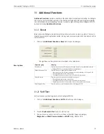
Page 77: ...gate SWG70 1 Click on the Additional Functions Self Test leaf to open the dialogue 2 Press the Perform Self Test button to start the test 3 The results can be seen in the first two sections of the HART diagnosis dialogue Diagnostics Wired Communication HART dialog Chapter 9 3 2 Parameter group Meaning Device Reset Press this button to restart Fieldgate without any impact on the established network...

Page 78: ...ade leaf to open the dialogue 2 Browse to the folder or location at which the firmware package is to be found ipk tar gz 3 Press to Upload the Package The following page appears 4 Press the Install the Package button to install the firmware To cancel the firmware upgrade press Discard Upgrade 5 The package will now be installed The installation process may take a while When the installation is fin...

Page 79: ...ks to the physical devices Any change must also be duplicated in the Set Device Addresses window see Chapter 8 6 7 otherwise the DTM is not able to establish a connection to the adapter Changes should be made only after all adapter DTMs have been closed The function is not relevant to FieldCare but might be required for other FDT frames 1 Right click on Fieldgate SWG70 node and select Additional F...

Page 80: ...ong Tag in WirelessHART networks to the one stored in the DTM The function is not relevant to FieldCare but might be required for other FDT frames 1 Right click on Fieldgate SWG70 node and select Additional Functions Set Device Addresses To change the device address 2 Place the cursor inside a cell of the Device Long Tag column 3 Change the device long tag as required You may change the long tags ...

Page 81: ...omputer is probably not connected to the Internet these should be available on its hard disk or a USB stick before the certificate is uploaded to Fieldgate SWG70 Now proceed as follows 1 Click on the Additional Functions Upload Certificate leaf to open the dialogue 2 Click Browse and select the certificate file on the hard disk or USB stick 3 Click to upload the certificate 4 The Upload Private Ke...

Page 82: ...FieldCare right click on the Fieldgate SWG70 node and select Observe The significance of the parameters is described in the table below Parameter Field Meaning Long Tag Identifies Fieldgate within the plant network For devices less than HART 6 0 the Message field is used as the long tag IO card Identifier of Fieldgate card used by the device Channel Identifier of card channel used by the device De...

Page 83: ...ed if repairs are required or if the wrong device has been ordered or delivered According to legal regulations Endress Hauser as an ISO certified company is required to follow certain procedures when handling returned products especially those that have been in contact with medium To ensure swift safe and professional device returns please read the return procedures and conditions on the Endress H...

Page 84: ...r away or an obstacle blocks the radio waves In this case add an additional device to bridge the gap 14 1 2 Eliminate Bottlenecks If the messages of several devices all have to pass through one single device to get to the gateway the network has a bottleneck If the device at the bottleneck fails whole parts of the network get cut off from communication because there are no alternative paths to rou...

Page 85: ...n between wireless devices add additional devices to provide alternative communication paths The more devices exist in a WirelessHART network the more reliable it becomes 14 1 4 Optimize Coexistence with other Wireless Networks WirelessHART networks IEEE 802 15 4 use the frequency spectrum between 2400 2483 5 MHz Various other wireless technologies also use this frequency spectrum for example WLAN...

Page 86: ...e Ethernet with a straight through connection although a crossover connection is necessary or vice versa Wire in accordance with the table in Chapter 5 3 The Ethernet parameters of the gateway are incorrect Check the gateway s Ethernet parameters see Chapter 8 3 2 The Local Area Connection Properties of your PC are not configured correctly Configure the Local Area Connection according to the instr...

Page 87: ...al strength by repositioning the antenna or adding adapters as repeaters Walls or other static moving objects block the radio signals or the antenna is not aligned vertically Reposition the gateway or use an external antenna 3 The Network ID and the Join Key cannot be downloaded to Fieldgate SWG70 The security DIP Switch 8 is OFF Set DIP Switch 8 to ON if Gateway installed in Ex Zone 2 switch off ...

Page 88: ...TCP communication Transmission rate 100 Mbit s max cable length 100 m at 25 C ambient temperature Type of protection None Galvanic isolation Fully isolated from all other circuits Maximum bus length 100 m 110 yds depending upon cable Connection facilities 7 port terminal block Screw terminals 0 2 mm2 to 4 mm2 for solid wire 0 2 mm2 to 2 5 mm2 for stranded wires 15 2 2 RS 485 serial interface Proto...

Page 89: ... 40 C to 85 C 40 F to 185 F Relative humidity 5 to 95 non condensing Vibration resistance EN 60068 2 6 1 Hz f 150 Hz 1 g Shock resistance EN 60068 2 27 15 g 11 ms Electromagnetic compatibility This device complies with the requirements of the EC Directive 2004 108 EG Electromagnetic Compatibility IEC 61326 Immunity EN 61326 1 2006 industrial environment Emission EN 61326 1 2006 Class A Telecommuni...

Page 90: ...ted aluminium Colour Light grey RAL 7035 Degree of protection IP 65 NEMA Type 4 Type of protection Complies with the requirements of the EC Directive 94 9 EG ATEX nA non sparking to EN 60079 15 2005 Cable entry 5 separate M16x1 5 threaded entries Antenna Omnidirectional dipole antenna Intrinsically safe antenna port Remote antenna available on request 228 8 98 257 10 12 57 2 24 Centers 240 250 9 4...

Page 91: ...gate SWG70 conforms to all relevant EU directives Telecommunication compliance Brazil ANATEL 2759 11 7311 EAN Number 7898994191414 China CMIIT ID SRRC ETSI R TTE FCC Part 15 247 for wireless applications in the 2 4 GHz frequency band Japan Ministry of internal affairs and communication Mexico COFETEL RCEPNSW12 0651 Other national certificates are available on request Additional national guidelines...

Page 92: ... the address of the intended receiver what this slave is to do data needed to perform the action and a means of checking for errors The slave checks if errors have occurred and performs the desired action After the action is performed the slave builds the response and returns it to the master The master can send another message to any slave as soon as it receives a valid response or after a user s...

Page 93: ...used for each register type For Fieldgate the holding registers are a read only image of the input registers which can be accessed when the Read Modbus Registers Mode is set to Input and Holding see Chapter 10 2 1 HART implementation The Modbus implementation in Fieldgate SWG70 maps HART dynamic process variables over Modbus input registers and also uses input registers to provide device related s...

Page 94: ... of WirelessHART devices in the network the response time of the devices and the number of parameters they transmit In general shorter refresh times can be attained by restricting the traffic over the network to essential parameters only 0 65535 0 0 0 Coils not supported by Fieldgate Discrete Inputs Input registers Holding registers for Fieldgate RO image of Input registers RW RW RO RO 1 65536 100...

Page 95: ... 1 175 10 38 to 3 403 1038 Byte Structure Storage Float Swapped Float Modbus Register 1 Modbus Register 2 Sign Exponent 8 bit Fraction 23 bit 31 0 23 0 15 31 16 31 16 0 15 Value range 0 to 65 535 Byte Structure Storage Unsigned Integer16 Swapped Unsigned Integer16 Modbus Register 1 Value 16 bit 15 0 0 15 0 15 Value range 0 to 255 Byte Structure Storage Unsigned Integer8 Swapped Unsigned Integer8 M...

Page 96: ... Ternary variable device specific unit 300021 300022 QV Quaternary variable device specific unit 300023 ModStat Modbus Specific Status 16 bit unsigned integer 300024 DevStat HART Device Status 300025 300026 AI Primary variable loop current mA unit 32 bit floating point 2 300027 300028 PV Primary variable device specific unit 300029 300030 SV Secondary variable device specific unit 300031 300032 TV...

Page 97: ...5 of the value with Index x The Index x is not determined by the position of a discrete value in the device s burst list but by its position in CMD 64385 For example if the 1st and 4th discrete variables are selected in the device s burst list the corresponding indices will be 0 and 3 Assuming that all bytes are of interest the user must enter the following lines Tag Device 1 Least Significant Byt...

Page 98: ...ster in the following sequence 47 F1 20 00 in big endian style where 00 the less significant byte is the first one to be transmitted The sequence can be changed to little endian see Chapter 10 2 1 A 3 2 Status mapping For each HART device two 16 bit unsigned input registers are used to map the relevant status information The status information is delivered as a series of independent flags Within a...

Page 99: ...x02 Device Variable Alert 0x04 Critical Power Failure 5 Device Operation in Progress Device specific status 5 0x02 Configuration Changed bit reset procedure 0x04 Sub Device update procedure 0x08 Device update procedure 6 Extended device status Not relevant for Gateway always set to 0 7 Device operating mode For future expansions always set to 0 8 Standardized status 0 0x01 Simulation active The de...

Page 100: ...ex of first Discrete Variable Returned 2 Unsigned8 Number of Discrete Variables returned n 3 Bits 8 Extended Device Status 4 7 Time Time stamp for most recent change to Actual Value of first Discrete Variable Value 8 9 Unsigned16 First Discrete Variable Value 10 Bits 8 First Discrete Variable Status 0x01 1 Discrete Variable in Simulation or Local Override 0x02 1 Discrete Variable in Fault Mode 0x0...

Page 101: ...each column If a mandatory column is missing the whole file is rejected and nothing is imported If a mandatory value is missing the corresponding data row is skipped B 2 Modbus Mapping CSV files The files for the MODBUS mapping contain the following columns The data in the RegisterType InformationCode and MappingCode columns is encoded as described in the tables below Register Type Codes Informati...

Page 102: ...tion is available and on the device specific unit codes see the manual of the subdevice 243 Battery Life 244 Percent Range 245 Loop Current 246 Primary Variable 247 Secondary Variable 248 Tertiary Variable 249 Quaternary Variable 255 Slot 0 data time stamp 3 MODBUS Status 0 Mod Stat information 4 Discrete Variable LSB 0 255 Discrete Variable Index The least significant byte of the variable is mapp...

Page 103: ...ry columns as there is no import function Nevertheless you can export the data in CSV format for documentation Expanded Device Type Code Device ID IO Card Channel Long Tag Status Device Status Number Of Joins Recent Join Date Reliability Latency Neighbor s RSSI Stability 4 digits hex 6 digits hex integer integer string 32 2 digits hex 2 digits hex integer yyyy mm dd hh mm ss float float string 32 ...

Page 104: ... Chapter 10 4 can access HART data from the same device or several different devices simultaneously The OPC client can subscribe to the data item of interest In addition it is possible for the client for example to only get the data item when it changes The HART OPC server is delivered with the product CD see Chapter 7 4 1 C 2 Creating an Ethernet network 1 Start the HART Server application Start ...

Page 105: ...COM port Baudrate and Retries 5 With Fieldgate SWG70 connected to the selected computer port right click on the network and select Add I O system NOTE For RS 485 you can press Add Multiplexer to invoke a similar procedure or Learn to automatically scan the network 6 The Add Device dialog appears Enter the IP Address of Fieldgate SWG70 default 192 168 1 1 Enter the Port default 5094 Enter the Poll ...

Page 106: ... 7 The IO System Properties dialog opens Press OK 8 The I O system is added to the project 9 Now right click on Fieldgate SWG70 node and select Learn The HART Server now scans the entire WirelessHART network Depending on how many devices are in the network this may take some time ...

Page 107: ... C Appendix HART OPC Connection Endress Hauser 105 10 After scanning is complete the network is added to Fieldgate SWG70 node The result should be similar to the screenshot above For more details on the structure see Chapter 3 3 1 ...

Page 108: ...r location of adapter up to 16 characters Message User message transmitted with information from Fieldgate SWG70 up to 32 characters Manufacturer Indicates manufacturer of Fieldgate SWG70 Model Indicates device type string name ID Indicates device identification Revs Indicates HART Universal Device Software and Hardware Revisions Operation Master Mode Indicates whether Fieldgate SWG70 is a primary...

Page 109: ...facturer of Fieldgate SWG70 Model Indicates device type string name ID Indicates device identification Revs Indicates Universal Revision Device Revision Software Revision Hardware Revision Properties Poll Address HART bus address Date Date on which the adapter was manufactured Number of Preambles Number of preambles for HART communication Operation Master Mode Indicates whether the adapter is a pr...

Page 110: ...dited to store changes press Send 3 The significance of the parameters can be taken from the table below Process Output parameters Parameter Meaning Process PV Indicates the current value of the primary variable Unit select Indicates changes the unit of the primary variable Loop Current Analog Value Loop current measured by adapter always 4 mA for HART multidrop Percent Range Primary value express...

Page 111: ...n or location of device up to 16 characters Date Indicates the date Final Assembly Number Indicates assembly number of device Write Protect Indicates whether write protect is in operation Private Label Distributer Indicates label of a private distributor Sensor Serial Number Indicates sensor serial number Sensor Info Upper Sensor Limit Indicates maximum value of the process variable that can be me...

Page 112: ...RT Info Manufacturer ID Indicates manufacturer ID of the device in plain text and as a hexadecimal number Device Type Indicates type of the device in plain text and as a hexadecimal number Device ID Indicates device ID as a hexadecimal number Request preambles Indicates number of preambles for HART communication HART Parameters Poll Address HART bus address Revisions Universal Revision Indicates u...

Page 113: ... the device memory Press Read to refresh the display 9 The significance of the parameters can be taken from the table below Status parameters Parameter Meaning Device Status Bit 0 to Bit 7 Standard HART status information A red dot indicates that the status is currently active Command 48 Info Indicates information received by when Command 48 is sent to the device More information is available in t...

Page 114: ...ance of the parameters can be taken from the table below Command parameters Parameter Meaning Request Command decimal Enter the number of the command to be sent The device must support this command Byte Count Indicates number of bytes sent with the command Data hex Data if any to be sent with the command Response Response Code decimal Indicates the command sent as a response to the request Byte Co...

Page 115: ... beneath the gateway in the project window Chapter B 3 1 Step 10 In the right part of the application window you can see the device connected to the selected channel 2 Right click on the device Select Data from the context menu 3 The Device Data window opens and displays all OPC data items 4 Close the window by pressing Close ...

Page 116: ... Data Spy client to view the data This is supplied with ControlCare Application Designer and is part of ControlCare P View 1 Open the client directly via Start Program or from the SCADA application 2 Expand the tree under HartServer HartOpc 1 down to the instrument tags 3 Select the Instrument Tag and click the 686 icon in the manu bar The Select an OPC Item dialog appears 4 Expand the tree down t...

Page 117: ...ssHART Fieldgate SWG70 C Appendix HART OPC Connection Endress Hauser 115 5 Select the tag then press OK the instrument data are displayed For more information on using OPC data see the P View operating manual ...

Page 118: ...D Appendix ANATEL Approval WirelessHART Fieldgate SWG70 116 Endress Hauser D Appendix ANATEL Approval ...

Page 119: ...WirelessHART Fieldgate SWG70 D Appendix ANATEL Approval Endress Hauser 117 For your notes ...

Page 120: ...D Appendix ANATEL Approval WirelessHART Fieldgate SWG70 118 Endress Hauser For your notes ...

Page 121: ...WirelessHART Fieldgate SWG70 D Appendix ANATEL Approval Endress Hauser 119 For your notes ...

Page 122: ...eas 4 I Identification 41 51 Input Register 68 Input Status 64 Installation 4 Instrument List 11 60 61 62 Interfaces 46 47 IP address 30 L LEDs 26 M Modbus interface parameters 49 Modbus RTU 90 Modbus Settings 63 Modbus TCP 90 Mounting 19 N Nameplate 8 Network management 10 Network optimization 82 O Online Paramaterization 41 OPC client 114 Operating elements 25 Overview 52 57 P Parameter 41 Power...

Page 123: ......

Page 124: ...www endress com worldwide ...

Reviews: