Windhager BioWIN XL BWE 350 NA Installation Instructions Manual Download Page 59

59

4. 

For the Service Technician

4.4.2  Start-up

The auger conveyor and the feed can be selected on the Start-up level with the 

arrow

 buttons, and confirmed 

using the 

choose

 button. A self-test is started at the end of the start-up.
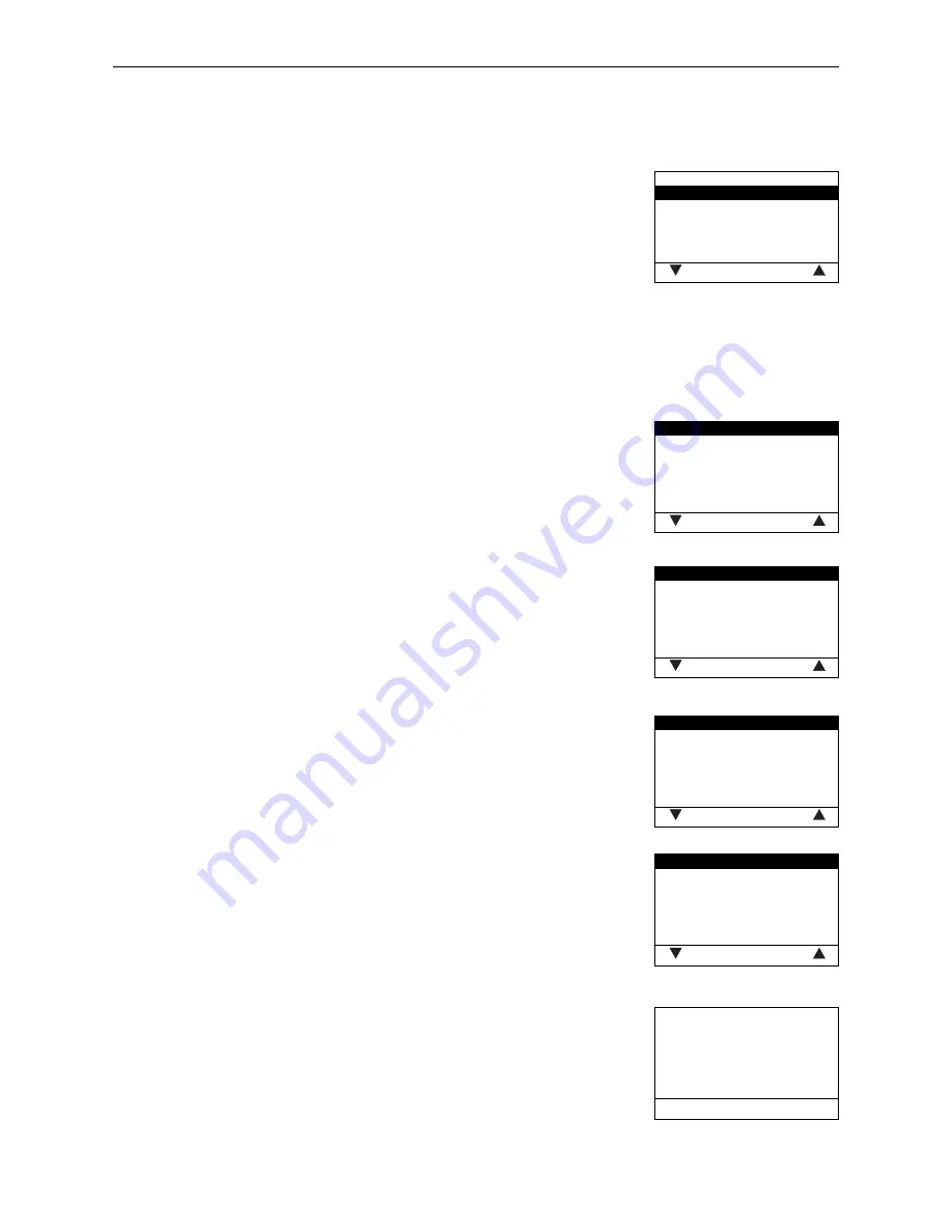
Fig. 138   

Start-up

Auger conveyor

Feed


choose 

back 

Auger conveyor

The auger conveyor can be turned on for 6 minutes.

Feed

Depending on the feed system settings, the feed and probes (including purging) 
can be started.

4.4.3  Actuator test

The following actuators can be selected with the

 arrow

 buttons, then confirmed and started using the 

choose


button. The actuators are turned off again after 1 minute. A self-test is started at the end of the actuator test.

Fig. 139   

Induced draught fan

Auger conveyor
Ash removal
Ignition element
Ash conveyor
Heating surf. cleaning


choose 

back 

–  Induced draught fan
–  Auger conveyor
–  Ash removal
–  Ignition element
–  Ash conveyor
–  Heating surf. cleaning
–  Suction turbine
–  Probe switching
–  Boiler pump

Fig. 140   

Suction turbine

Probe switching
Boiler pump


choose 

back 

4.4.4  Settings

This sub-menu contains the following settings: 
–  Install display module
–  Boiler no.
–  Language selection
–  Temperature format
–  Time format
–  Date format
–  Weight
–  Function

Fig. 141   

Install display module

Boiler no.
Language selection
Temperature format
Time format
Date format


choose 

back 

Fig. 142   

Weight

Function


choose 

back 

Install display module

The install display module is not needed for an individual boiler; it only needs to 
be used for a cascade system.

Fig. 143   

Start installation procedure

Please press LON button on auto-
matic firing device briefly


back 

Summary of Contents for BioWIN XL BWE 350 NA

Page 1: ...nstallation Instructions BioWIN XL FOR USE IN CANADA USA 03 2015 094886 01 Pellet central heating boiler furnace FOR USE IN CANADA USA 03 2015 094886 01 Pellet central heating boiler furnace SAVE THES...

Page 2: ...pressure loss 15 2 4 Combustion air 16 2 4 1 Operating with room air 16 2 4 2 Operating independently of the room air 16 2 5 Installation sequence 18 2 6 Setting up preparing for installation 18 2 7...

Page 3: ...4 Service level 53 4 4 1 Parameters 56 4 4 2 Start up 59 4 4 3 Actuator test 59 4 4 4 Settings 59 4 4 5 Installation of MESPLUS modules 61 4 5 InfoWINPLUS basic settings 61 5 Technical Data 64 5 1 Te...

Page 4: ...llation should be performed only by appropriately qualified technicians DANGER Please follow the safety instructions symbols on the machine Please refer to the instructions in chapter 1 1 4 DANGER The...

Page 5: ...heating chamber door can crush and cut When opening door never insert hands between the door and frame on the hinge side of the heating chamber CAUTION Closing heating chamber door can crush and cut W...

Page 6: ...water and hot steam Injury hazard Safety devices such as the relief valve will open automatically and release hot water or hot steam Keep away from safety devices Do not operate safety devices manuall...

Page 7: ...heat resistant gloves Use tools provided WARNING Health hazard Combustion particulates may contain harmful substances Use a fine dust face mask during cleaning WARNING Rotating parts can crush and di...

Page 8: ...ubstances known to cause cancer birth defects death serious illness or other reproductive harm in propositions This product may con tain such substances either from the fuel fuel combustion or in comp...

Page 9: ...and installation instructions Minimum clearances from combustible or noncombustible construction 2 inches left 12 inches back 24 inches top right 6 inches right side 22 inches front Access to the back...

Page 10: ...ng areas The minimum draft required at the flue gas collar is 0 02 in H2O 0 05 mbar The maximum draft allowed at the flue gas collar is 0 08 in H2O 0 2 mbar The minimum flue pipe diameter required is...

Page 11: ...t probe and pellet boiler heater with max total height difference of 9 2 ft 2 8 m Max distance of 33 ft 10 m between furthest probe and pellet boiler heater with max total height difference of 14 8 ft...

Page 12: ...plastic sack Fig 3 The cladding parts are in a separate cardboard box Cleaning tools are packed in the combustion chamber and the ash chamber In addition the pellet feed unit is packed in several card...

Page 13: ...cumulatorr tank min 100 gal is mandatory a return hold up group boiler protection group 113 F 45 C is mandatory To ensure the boiler minimum temperatures and the pump lag time the transfer hot water t...

Page 14: ...ing systems are comprised of different materials Therefore a water treatment is recommended to prevent or limit problems metal corrosion calcification and sludge formation microbiological contaminatio...

Page 15: ...d residues from the heating circuit In the case of cleaning with chemical products the above points are especially important for avoiding any residues from corrosive products In the event of considera...

Page 16: ...supplied directly from the installation room If combustion air is drawn directly by the system from the boiler heater room the room must be adequately ven tilated The combustion air should be directed...

Page 17: ...cting piece flue gas 4 Air flue gas system Detail X Y Opening shaft head in accordance with DIN V 18160 1 DH flue gas diameter H spacing of opening HA spacing of dispersion plate E protrusion of dispe...

Page 18: ...ammable surface and does not require special foundations If foundations have been provided we recommend that they be made according to the boiler dimensions to ensure that the four set screws make con...

Page 19: ...Cladding door right 9 Base panel 10 Centre panel horizontal 11 Cladding door left 12 Auger tube rotary feeder unit 13 Access ramp 14 Floor plate 15 Integral fuel hopper support 16 Integral fuel hopper...

Page 20: ...the rear Fig 13 Remove support for integral fuel hopper part 15 from boiler by removing transport attachments cable ties Fig 14 Unscrew auger tube rotary feeder part 12 with transport attachments she...

Page 21: ...de sensor for auger tube safety thermostat together with sensor guard Fig 19 into sensor holder as far as it will go Fig 20 Connect 3 pin plug for rotary feeder proximity switch Fig 21 Fig 19 Sensor a...

Page 22: ...ig 23 Fitting the integral fuel hopper Remove 1 TT screw M8 x 16 from the floor plate Fig 26 and use it to mount the one support attached to the side of boiler on the floor plate Fig 24 Tightening 2 T...

Page 23: ...TT screws M5 x 12 Fig 31 and full fill level switch at top rear of hopper with 4 TT screws M5 x 12 Fig 32 Fig 29 Plugs for auger motor and fill level switch Fig 30 Connecting plug for auger motor Fig...

Page 24: ...nel Fit vertical center panel part 21 Fig 37 remove 2 x prefitted TT screws at bottom Fig 38 Fig 35 Fitting right side panel view from below Fig 36 Threading InfoWINPLUS cable into side panel Fig 37 F...

Page 25: ...tical center panel with 2 self tapping screws Fig 41 Fit horizontal center panels part 10 secure each panel with 4 self tapping screws Fig 42 Mount base panel part 9 with 2 self tapping screws Fig 43...

Page 26: ...w Fig 45 Sliding anti contact protection plate into guide slot Fit left side panel part 18 at bottom position cut out in base Fig 48 Secure side panel to the hopper at the top rear using 1 prefitted T...

Page 27: ...ws Fig 51 Mounting hopper cladding at top right Fit cover of integral fuel hopper part 20 secure with 2 self tapping screws at front Fig 54 and secure at rear with 2 prefitted TT screws M5 x 12 Fig 55...

Page 28: ...h a saw tooth ring for grounding Fig 61 and 3 nuts Fig 62 Fig 58 Fitting both hinges on cladding door Fig 59 Mounting cladding door with hinges on right side panel Fig 60 Threading InfoWINPLUS cable i...

Page 29: ...Fig 63 Attaching grounding cables and saw tooth ring to cover Fig 64 Connecting InfoWINPLUS plug and at taching grounding cables Fig 65 Reattaching the cladding door cover Screw grounding cables to co...

Page 30: ...h BioWIN XL 350 NA only in on burner pot Mount left cladding door part 12 on integral fuel hopper Fig 69 Attach access ramp part 14 for ash container with 2 prefitted TT screws M5 x 12 Fig 70 Fig 68 C...

Page 31: ...nts on a wall in the boiler room Fig 75 Fig 73 Closing the bracket fastener Fig 74 Closing the cladding door with the key Closing the bracket fastener Fig 73 Close left cladding door and turn key a qu...

Page 32: ...To do this unfasten 2 screws turn the orifice orifice fully open 0 and retighten the screws Fig 77 Fig 76 Mounting the intake fitting Fig 77 Setting the orifice in the intake fitting to the value on t...

Page 33: ...xhaust line particularly after 3 28 ft 1 m length should be insulated in order to prevent or minimise condensation INFORMATION Any section of this exhaust line that is horizontal or inclined less than...

Page 34: ...tic changeover unit with cover plate 3x suction probes Part Quantity Designation 4 M8 x 30 hexagon screw 4 M8 x 30 brass dowel 4 U washers 8 10 6 x 50 hexagon head wood screws 6 U washers 6 4 U washer...

Page 35: ...floor in sequence Fig 82 B1 Return air hose A1 Supply hose 1 Storage room door 2 Wooden boards 3 Suction probes 4 Filling pipe 5 Return air pipe 6 Automatic changeover unit 7 Supply and return air hos...

Page 36: ...not be laid in an up and down manner This could cause bags to form preventing the pellets from flowing smoothly Use the shortest route from the storage room to the feed unit and lay the hoses in such...

Page 37: ...ion hazard Can lead to serious injury death Ground suction hoses must be installed as de scribed in the installation instructions at every connection to avoid static sparking dust ignition The pellet...

Page 38: ...dowels a fire protection tested injection system must be used to attach the changeover unit Wall duct for changeover unit Make a feed through hole approx 8 66 in 220 mm in diameter for the changeover...

Page 39: ...to the front of the changeover unit B It then passes from the rear of the changeover unit B1 B2 and B3 back to the probes B1 B2 and B3 Overview of connection to the BioWIN XL B1 B2 B3 A3 A2 A1 B A 1 2...

Page 40: ...n the same way for all other hoses A2 A3 B1 B2 and B3 2 Fit cover plate inside storage room Drill 4 mounting holes 0 31 inch 8 mm in diameter Insert 4 x F8 screw anchors Temporarily screw down the cov...

Page 41: ...corresponding connections on the changeover unit The flexible ground leads must be in contact with their connections Secure the hoses with hose clips Fig 92 INFORMATION To make fitting the hoses easi...

Page 42: ...rew down the cover plate inside the storage room Fig 95 Fig 94 Filling masonry feed through with mineral wool Fig 95 Fitting the cover disc 6 Connect delivery hoses to probes Connect the labeled hoses...

Page 43: ...ry hoses in plastic tubes Fig 98 Connection of changeover unit 1 31 5 in 80 mm plastic tubes 2 Do not clamp hoses tightly 3 There must be at least 4 76 ft 1450 mm of hose before the first fastening po...

Page 44: ...8 x 60 2x U washer 8 2x dowel 10 2 10 6 2 Suction turbine The hose connection 3 to the changeover unit can be turned through up to 180 to the other side To do this rota te the top cover 1 clockwise an...

Page 45: ...inwards into the hose Fig 104 6 3 in 160 mm 6 3 in 160 mm 4 65 in 118 mm 10 3 in 270 mm Fig 103 Dimensional drawing of suction turbine Fig 104 Exposing flexible earth leads bending inwards 5 Rotate th...

Page 46: ...orage room door Every time the storage room is filled record the date and volume on the Filling date and volume sticker Fig 107 Stickers for storage room door Bef llung Lagerraum Filling date and volu...

Page 47: ...tally friendly and energy saving operation The following preconditions must be met before ordering the commissioning 1 Boiler installed correctly 2 System fully electrically wired 3 System rinsed fill...

Page 48: ...layed action fuse On site the technician must install an all pole disconnect with at least a 0 12 in 3 mm contact gap at the main access point All electrical connections are located in the control pan...

Page 49: ...PLUS cable Fig 110 Loosening screw at front and removing control panel cover Fig 111 Folding up top part of control panel 3 1 1 Opening and closing the control panel Loosen 1 screw on top of control p...

Page 50: ...changeover unit 230 V AC external control 3 1 3 2 Operation with external control with buffer only a Heating requirement setpoint specification with 2 point controller The 2 point controller switches...

Page 51: ...unit The cables must not be too short or under tension in the cable ducts For connection diagrams for the suction turbine and changeover unit see section 6 electrical connection diagrams Connection be...

Page 52: ...ly without power When replacing system components pumps mixing valves etc stop all power input e g disconnect main power via circuit breaker Please note Disconnect the main circuit breaker before open...

Page 53: ...Profile ash removal Correction of cleaning interval Flue gas thermostat or Air intake flap Limits for blower speed Minimum operating time with buffer Parameters Operator level Settings on the operator...

Page 54: ...se back Fig 119 Operator level Service level Information level MES Module1 choose back Fig 120 Service level only for trained service personnel 5s Use the arrow buttons to select Service level Fig 118...

Page 55: ...the choose button to confirm the choice Fig 121 For further settings see chapters 4 4 1 4 4 4 Fig 121 Parameters Start up Actuator test Settings choose back Fig 122 Parameters Start up Actuator test...

Page 56: ...umber of burner starts Fuel quantity auger conveyor Delivery time ignition phase Hysteresis Burner ON Maximum value of set temperature Set temperature ext heating requirement Type of pellet feed syste...

Page 57: ...urbine with 3 probes Europe only For changeover unit with 8 probes Suction turbine with 4 probes Suction turbine with 6 probes Suction turbine with 8 probes For buried tank with mixer Suction turbine...

Page 58: ...e back Flue gas thermostat or air intake exhaust flap This setting can be used to change the flue gas thermostat function factory setting to the air intake exhaust flap function Factory setting Flue g...

Page 59: ...139 Induced draught fan Auger conveyor Ash removal Ignition element Ash conveyor Heating surf cleaning choose back Induced draught fan Auger conveyor Ash removal Ignition element Ash conveyor Heating...

Page 60: ...ratures are displayed in the chosen format e g 87 0 F or 30 6 C Factory setting C Selection C and F Fig 147 Time format 24h 12h save back Time format The time is displayed in the chosen format e g 14...

Page 61: ...are available in the basic settings Language selection Boiler MB SMS ELG Ethernet Update Software Update Firmware Display contrast Fig 152 Boiler temperature Operating phases Info Menu 107 F Fig 153 V...

Page 62: ...ultiWIN only master operation for remote switching Fig 157 MB Yes No save back MB Master operation Setting to define whether MESplus system control is present Factory setting is set in the factory bef...

Page 63: ...face is being started Fig 162 Update Firmware start back Update Firmware The update procedure to update the LON Controller firmware is being started The LON Controller firmware is included in the Info...

Page 64: ...es from type test Testing office T V S D Munich test report no H C4 1190 00 11 and H C5 1190 00 11 Firing efficiency Rated load 100 qA Part load 93 1 94 7 91 8 92 8 92 5 94 0 Boiler efficiency Rated l...

Page 65: ...LQ PP 5RKU 5 FNOXIW LQ PP 5RKU 7 HVVHO 7HPSHUDWXUI KOHU XOXIW Fig 164 BioWIN XL pellet boiler KV Boiler feed 5 4 pipe KR Boiler return 5 4 pipe TV Thermal valve sensor 1 2 sleeve SB Safety device 1 2...

Page 66: ...6 5 4 3 2 1 2 1 2 1 3 2 1 3 2 1 Lon Lon GND 12V 3 2 1 GND Lon Lon 12V 1 2 3 1 2 1 2 3 4 1 2 3 1 2 3 4 1 2 1 2 3 4 5 6 1 2 3 1 2 3 1 2 1 2 3 4 FA BioWIN XL L N PE L N LL N PE RL L L L N PE L N PE N PE...

Page 67: ...230 VAC low voltage 110V 120V 60Hz extra low voltage 12V 22 21 42 41 X2 emergency heating off switch M PE LL RL N PE changeover unit M9 1 motor 21 EH 22 EH 8 CP 18 LL 12 L optional accessories PE 9 N...

Page 68: ...r boiler circuit pump P3 1 PE Heating Zone Controller heat demand 4 3 PE max rated 200W XE 8 external heat demand conn diagram 1 7B XE 9 external heat demand conn diagram 1 7B XE 10 L Transfer boiler...

Page 69: ...2 L2 N Connection 120 V 60 Hz or Connection 3 x 230 V 60 Hz external feeder cable must be laid by an electrician 230 VAC 120 VAC M PE L N suction turbine 110 120 V PE M12 1 Connection for buried tank...

Page 70: ...diagram for air intake exhaust flap The air intake exhaust flap is directly connected to the main PCB see basic circuit diagram 4 8 at plugs X4 motor and X14 limit switch See section 4 6 1 Para meters...

Page 71: ...mostat The flue gas thermostat is directly connected to the main PCB see basic circuit diagram 4 8 at plugs X4 motor and X14 limit switch See section 4 6 1 Parame ters Flue gas thermostat or Air intak...

Page 72: ...to technical modifications AWP vor Austria Windhager Zentralheizung GmbH Anton Windhager Stra e 20 A 5201 Seekirchen bei Salzburg T 43 0 6212 2341 0 F 43 0 6212 4228 info at windhager com www windhag...

Reviews: