Williamson-Thermoflo SCH High Boy Manual Manual Download Page 6


SCH & SCL 

Oil Furnaces

 – 

Furnace Manual


6


 670-000-006-1007


3


Connect supply and return ducts 


Duct sizing 

Determine air flow CFM 

The temperature rise through the furnace must not exceed 85

o

 F and 

should be at least 55°F for comfort. When calculating air flow, 
assume a temperature rise of 70°F. 

The sensible heat temperature change for cooling would be 
approximately 27-30°F. Actual temperature change will be 
approximately 18-21°F due to humidity of the air. 

To calculate the sensible heat temperature change (

Δ

T), you can 

use the formula: 

Δ

T = BTU/h/(1.1 x CFM) 

Eq. 3-1 

To calculate air flow when you know temperature change (

Δ

T), you 

can use:  

CFM = BTU/h/(1.1 x 

Δ

T) Eq. 

3-2 

You can estimate air flow using the following rules of thumb:  

Heating:  

14 CFM per 1,000 BTU/h

 output 

Eq. 3-3 

Cooling: 

400 CFM per ton

 air conditioning 

Eq. 3-4 

Determine the required air flow based on whichever is larger – 
heating mode or air conditioning mode. 
 
Examples:  

1.

  What would the temperature rise be for a 100,000 BTU/h output 

furnace with an air flow rate of 1200 CFM? 

Use Equation 3-1 since you know CFM and BTU/h: 

Δ

T = 100,000/(1.1 x 1200) = 76°F 


The temperature rise would be 76°F. 

  If the air enters the furnace at 70°F, it would leave the 

furnace at 70°F + 76°F = 146°F. 

2.

  What would the air flow be to obtain a 70°F rise through a 

120,000 BTU/h output furnace? 

Use equation 3-2 since you know 

Δ

T and BTU/h: 

CFM = 120,000/(1.1 x 70) = 1,558 CFM 

  The air flow would have to be 1,558 CFM to obtain a 

temperature rise of 70°F. 

3.

  Estimate the required air flow for a 75,000 BTU/h output furnace 

installed with a 2-ton air conditioning evaporator coil. 

Heating mode air flow (use Equation 3-3): 

CFM = 75 x 14 = 1,050 CFM 

Cooling mode air flow (use Equation 3-4): 

CFM = 2 x 400 = 800 CFM 

  The larger number is 1,050 CFM (heating), so the duct 

system should be sized for 1,050 CFM. 


The supply duct would need to be 16

"

 round or a rectangular 

equivalent such as 8

"

 x 25

"

 or 12

"

 x 16

"

, using Table 4, page 

7. 

4.

  Estimate the required air flow for the same furnace installed with 

a 4-ton air conditioning evaporator coil. 

Heating mode air flow is still 1,050 CFM. 

Cooling mode air flow (use Equation 3-4): 

CFM = 4 x 400 = 1,600 CFM 

  The larger number is 1,600 CFM (cooling), so the duct 

system should be sized for 1,600 CFM. 


The supply duct would need to be 18

"

 round or a rectangular 

equivalent such as 8

"

 x 36

"

 or 12

"

 x 21

"

, using Table 4, page 

7. 


Always check the size of existing ducts, particularly 
if you are adding air conditioning. The air pressure 
loss through the cooling evaporator coil reduces 
available air flow. If the ducts are too small as well, 
the system may not work satisfactorily on either 
heating or cooling. 

CAUTION 


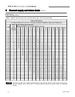
Determine duct dimensions 

Table 4, page 7 and Table 5, page 8, provide typical round and 
rectangular duct sizes for rectangular and flat oval galvanized ducts. 
Do not apply these tables to size ductwork if the total equivalent 
length of the duct exceeds approximately 100 feet. For longer 
systems or for duct board, fiberglass-lined or flexible duct sizing, use 
the ACCA Manual D or the ACCA duct sizing slide rule. These 
tables are based on pressure loss of approximately 0.10 inch water 
column per 100 feet equivalent length of duct. 

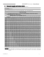
Use Table 3 below to size or check sizing of take-offs to supply 
registers or return grills. 

Verify the size and type of registers, diffusers and grills from the 
manufacturer’s ratings. Do not exceed the recommended flow rate. 
The pressure drop allowance for each should not exceed 
approximately 0.05 inch water column. 

Install a return air filter, sized per specifications in Section 12. 

Use only a return air filter mounted to the furnace. Do not add 
additional filters unless the duct system is carefully sized to allow for 
the additional pressure drop. 


Table 3

  Suggested maximum flow to runouts 


TAKE-OFF SIZE

(Inches)

SUPPLY

RETURN

5 Round

60

45

6 Round

100

75

7 Round

140

110

8 Round

210

160

3 ¼ x 8 Stack

70

55

3 ¼ x 10 Stack

100

75

3 ¼ x 14 Stack

140

110

2 ¼ x 12 Stack

70

55

2 ¼ x 14 Stack

90

70

6 Round

55

40

8 Round

120

90

10 Round

200

160

12 Round

320

250

14 Round

480

375

16 Round

660

530

18 Round

880

680

20 Round

1200

900

CFM

Sheet metal or ductboard

Flexible duct (keep bends to minimum)

Summary of Contents for SCH High Boy

Page 1: ...against the transportation company by the consignee Do not store or use gasoline or other flammable liquids or vapors near this furnace or any other appliance Ventilate house while operating furnace f...

Page 2: ...mixture of gasoline and oil waste fuel refuse or any other substance in the burner of furnace Installation 18 Do not block flow of combustion or ventilation air to furnace Do not block or obstruct th...

Page 3: ...ccessibility NOTICE NOTICE Flooring and foundation Flooring SCH SCL furnaces are approved for installation on combustible flooring but must never be installed on carpeting Do not install furnace on ca...

Page 4: ...nd flue gas outlet of a direct vent appliance shall terminate at least 1 ft 0 3 m from the soffit of the roof of the structure and at least 3 ft 0 9 m from an inside corner of an L shaped structure Th...

Page 5: ...m and air conditioning evaporator coil if used must not exceed 0 5 inch water column Openings in walls floor continued See suggested duct sizing in this manual For more detailed sizing information ref...

Page 6: ...stalled with a 4 ton air conditioning evaporator coil Heating mode air flow is still 1 050 CFM Cooling mode air flow use Equation 3 4 CFM 4 x 400 1 600 CFM The larger number is 1 600 CFM cooling so th...

Page 7: ...12 11 10 10 9 9 8 1400 18 63 47 38 31 27 24 19 16 14 13 12 11 10 10 9 9 1500 18 68 51 40 34 29 25 20 17 15 14 12 12 11 10 10 9 1600 18 72 54 43 36 30 27 21 18 16 14 13 12 11 11 10 9 1700 18 58 45 38...

Page 8: ...30 26 24 20 18 1400 18 62 47 38 32 28 25 21 18 17 1500 18 66 50 41 34 30 26 22 19 18 1600 18 71 54 43 36 31 28 23 20 18 1700 18 57 46 38 33 29 24 21 19 1800 18 60 48 40 35 31 25 22 20 1900 20 63 50 42...

Page 9: ...g will be routed from the furnace 2 The flexible venting has 4 pieces of corrugated spin sleeve that has been temporarily screwed over top of it Remove the spin sleeve completely by unscrewing it in a...

Page 10: ...be removed to access the top right wall plate screw hole For concrete and block Tapcon screws or equivalent are recommended Install the wall plate so that the top of the hole in the wall plate is posi...

Page 11: ...r If the optional vestibule was installed remove the appropriate knockouts in the side panels of the vestibule The lower 5 inch knock outs in the right hand panel is used for the Beckett AFII burner T...

Page 12: ...SCH SCL Oil Furnaces Furnace Manual 12 670 000 006 1007...

Page 13: ...SCH SCL Oil Furnaces Furnace Manual 670 000 006 1007 13...

Page 14: ...SCH SCL Oil Furnaces Furnace Manual 14 670 000 006 1007...

Page 15: ...is factory wired to the furnace at the factory Plug the burner harness into the mating burner connector to wire the burner Refer to the wiring diagram on pages 16 and 17 for further information Insta...

Page 16: ...SCH SCL Oil Furnaces Furnace Manual 16 670 000 006 1007 6 Wire furnace burner continued Figure 2 Wiring SCH SCL furnaces with direct drive blower DNS 0988 Rev D...

Page 17: ...SCH SCL Oil Furnaces Furnace Manual 670 000 006 1007 6 Wire furnace burner continued Figure 3 Ladder wiring SCH SCL furnaces with direct drive blower DNS 0890 Rev C 17...

Page 18: ...with 0 smoke To take an overfire pressure reading replace the sight glass assembly with the washer supplied with the appliance After having taken the reading put the sight glass back see Figure 2 To s...

Page 19: ...lower speed adjusted if necessary 19 Thermostat heat anticipator set per wiring diagram 20 Burner started and tested per burner manual 21 Proper draft and burner flame Final adjustment made with combu...

Page 20: ...d________________________ Installation instructions have been followed Checkout sequence has been performed Above information is certified to be correct Information received and left with owner mainte...

Page 21: ...transformer output Reference burner manufacturers instructions Check tube insertion and alignment Check nozzle and electrode position Reference burner manufacturer s instructions Replace nozzle Check...

Page 22: ...es given on page 20 Failure to comply could result in severe personal injury death or substantial property damage WARNING Consult with homeowner to see if there were any Check sequence of operation pr...

Page 23: ...in a plastic bag for disposal Wash potentially contaminated clothes separately from other clothing Rinse clothes washer thoroughly NIOSH stated First Aid Eye Irrigate immediately Breathing Fresh air...

Page 24: ...ll up the oil cup Over oiling can damage the motor Annual start up Follow information below to prevent severe personal injury death or substantial property damage DANGER Do not use gasoline crankcase...

Page 25: ...SCH SCL Oil Furnaces Furnace Manual 670 000 006 1007 COMPONENTS AND REPLACEMENT PARTS 25...

Page 26: ...SCH SCL Oil Furnaces Furnace Manual 26 670 000 006 1007 11 Components and replacement parts Figure 3 Model SCH 105 furnaces Component locations B50016A...

Page 27: ...BLY FRONT 21 B30761 INSULATION FRONT PANEL 22 B30808 ELECTRICAL BOX COVER ASSEMBLY 23 B30515 01 FLANGE 3 FLUE OUTLET ASSEMBLY 24 Z99F050 RECESSED HANDLE BLACK 25 B30455 01 BOTTOM FRONT PANEL ASSEMBLY...

Page 28: ...SCH SCL Oil Furnaces Furnace Manual 28 670 000 006 1007 11 Components and replacement parts Figure 4 Model SCH 160 furnaces Component locations B50015 Rev A B50015A...

Page 29: ...ESS COVER GASKET 24 B30415 01 ACCESS COVER GASKET 25 B30487 01 BREECH PLATE WITHOUT HOLES 26 B30533 BREECH PLATE GASKET 27 B30652 01 REAR PANEL ASSEMBLY 28 B30659 REAR PANEL INSULATION 29 B30653 03 PA...

Page 30: ...SCH SCL Oil Furnaces Furnace Manual 30 670 000 006 1007 11 Components and replacement parts Figure 5 Model SCL 105 Rear furnaces Component locations B50018A...

Page 31: ...RIGHT 24 B30509 03 PANEL ASSEMBLY RIGHT SIDE 25 B30493 03 PANEL INSULATION RIGHT SIDE 26 B30534 GASKET BURNER 27 B30808 COVER ELECTRICAL BOX 28 B30533 GASKET SEALING PLATE 29 B30415 01 GASKET HEAT EXC...

Page 32: ...SCH SCL Oil Furnaces Furnace Manual 32 670 000 006 1007 B50018A 11 Components and replacement parts Figure 6 Model SCL 160 Rear furnaces Component locations B50017 Rev A B50017A...

Page 33: ...IDER PLENUM 25 B30680 03 PANEL ASSEMBLY RIGHT SIDE 26 B30686 01 PANEL INSULATION RIGHT SIDE 27 B30668 01 FILTER SUPPORT BOTTOM RIGHT 28 B30665 BAFFLE FRONT 29 B30415 02 GASKET HEAT EXCHANGER 30 B30534...

Page 34: ...1 100 1 000 blower 100 800 83 900 X 0 60 60W 80 3 Med Low 1 100 1 000 speed 119 000 97 000 0 75 70B 0 75 70B 82 2 Med Low 1 350 1 310 5 tons 135 800 110 000 0 85 70B 0 85 70B 81 5 Med Low 1 350 1 310...

Page 35: ...gh 1 090 1 000 blower 100 800 84 200 X 0 60 60W 80 3 Med High 1 090 1 000 speed 119 000 97 000 0 75 70B 0 75 70B 82 2 Med Low 1 360 1 350 5 tons 135 800 110 000 0 85 70B 0 85 70B 81 5 Med High 1 625 1...

Page 36: ...el AFII 85 3450 RPM Tube insertion 4 15 16 Model SCH SCL 105 RIELLO BURNER Model 40 BF3 Tube insertion 5 3 16 Model SCH SCL 105 Combustion Model SCH SCL 160 burner data Pump Combustion Input Firing ra...

Page 37: ...1350 1310 MED HI 1300 1150 1605 1510 HIGH 1550 1350 2060 1825 SPEED SCH 105 SCH 160 EXTERNAL STATIC PRESSURE EXTERNAL STATIC PRESSURE WITH AIR FILTER WITH AIR FILTER 0 25 W C 0 5 W C 0 25 W C 0 5 W C...

Page 38: ...ame failure the burner primary control will lock out Ask your service technician to show you the correct procedure to reset the primary control button NEVER push the button more than once in an attemp...

Page 39: ...SCH SCL Oil Furnaces Furnace Manual 670 000 006 1007 X40132 Rev D 39...

Reviews: