


SCH & SCL
Oil Furnaces
–
Furnace Manual
10
670-000-006-1007
4
Venting – Sealed Combustion System
(continued)
Connection to the vent terminal
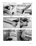
1.
Prepare the terminal end of the insulated flex vent by first
screwing the spin sleeve onto the corrugated aluminum
jacket until the trailing edge of the spin sleeve is about 10
inches from the end of the vent;
2.
Using sharp tin snips, cut the aluminum outer sleeve back
by 5 inches on the IFV Series vent;
3.
Pull the insulation back to expose the corrugated stainless
steel core;
4.
Cut the corrugated stainless steel core back by 3 inches on
the IFV Series vent. You should now have about 3 inches of
insulation hanging out past the stainless steel core;
5.
Push the stainless steel core onto the pipe on the back of
the terminal as far as it will go and mechanically attach the
vent to the terminal using three of the #8 x 1/2" self-drilling
screws provided with the VTK Series kit. The screws should
be equally spaced around the circumference of the stainless
steel core, starting with the first screw at top dead center.
Start the drill point of the screws in the valleys of the
corrugations at 3/8"-5/8" back from the end of the stainless
steel core;
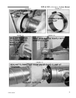
6.
With the stainless steel core now firmly attached to the
terminal, apply sealant all around the joint where the
corrugated stainless steel core meets the smooth outer
surface of the breach pipe (see Figure 1.7). In other words,
the sealant must be centered over the joint;
7.
Also, make sure that the heads of the self-drilling, stainless
steel screws are completely covered with the sealant;
8.
Position the other stainless steel band clamp over the
sealant so that the edge of the clamp closest to the terminal
lines up with the edge of the sealant that is closest to the
terminal. Tighten the band clamp with considerable torque to
cause the sealant to be squeezed into all crevices and to
ooze out of the end of the clamp closest to the terminal (see
Figure 1.11);
9.
The seal is permanent and should never need to be
disconnected as the end of the terminal can be opened for
cleaning and inspection by removing the screened end-cone
assembly. Tuck the vent insulation into the recess in the
terminal body;
10.
Screw the spin sleeve tightly into the recess for a finished
appearance. Wrap the other end of the spin sleeve with
aluminum tape to cover any metal burrs that may be present
(see Figure 1.12);
11.
Bend the venting into the desired radius coming off the
terminal.
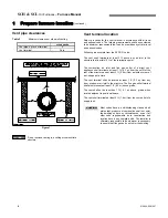
Installing terminal in the wall
1.
Cut a 6 inch hole in the side-wall in accordance with the
location considerations outlined in the previous section;
2.
Fasten the wall plate to the inside-wall using 4 field-provided
fasteners, appropriate for the material behind the wall plate.
Depending on the angle of access, the pressure control
bracket may need to be removed to access the top right wall
plate screw hole. For concrete and block, Tapcon™ screws
or equivalent are recommended. Install the wall plate so that
the top of the hole in the wall plate is positioned 1/8” lower
than the top of the 6 inch hole in the wall. This will
accommodate the proper downward slope of the terminal, in
the direction from the inside to the outside;
3.
Remove the 2 screws fastening the end cone in place and
remove the cone;
4. Remove the 2 screws fastening the stabilizer shroud in
place and remove the stabilizer shroud;
5.
Insert the main body of the terminal through the wall plate so
that the end of the terminal extends about 2 inches past the
outside wall;
6.
Install the stabilizer shroud and replace the two mounting
screws. (see Figure 1.13);
7. On concrete and block wall installations in particular, if it
appears that the flange on the back of the stabilizer shroud
is not large enough to cover the irregularities in the hole, a
field fabricated wall plate can be constructed out of 304,
316, or 316L stainless steel;
8. Silicone seal the circumference of the joint where the
stabilizer shroud connects to the main body of the terminal;
9.
Apply caulking to the back plate of the stabilizer shroud and
push the terminal back firmly against the wall, making sure
the pressure switch is located at the top, in a horizontal
position;
10. While pushing down gently on the top of the stabiliser
shroud, install the 3 stainless steel 2 inches screws provided
with the kit to secure the back of the shroud to the wall. Do
not overtighten the screws or it will distort the stabiliser
shroud. The screws will not be necessary in a concrete or
block wall as the mortar can provide positive positioning;
11. Tighten the clamp on the wall plate to secure the terminal in
place;
12. Apply more caulking all around the seam where the
stabilizer shroud meets the wall. It is important to have a
good seal to prevent water from entering the dwelling (see
Figure 1.14). A considerable amount of caulking may be
necessary for irregular wall surfaces such as lapped siding;
13. Install the end cone and replace the two mounting screws;
14. Support the vent and intake air piping so that a 1/4" to 1/2"
downward slope (toward the outside) results for proper
drainage out the terminal body.
Ducted outdoor combustion air (Sealed Combustion System)
The burners are set up to duct outside combustion air directly to
the burner: the Beckett AFII and the Riello 40-BF for side-wall
venting.
The use of ducted outside combustion air is
mandatory with side-wall venting systems. The
system operates on a balanced flue principle
and will not function properly if the combustion
piping is not attached and sealed at all
connections between the vent terminal and
burner inlet.
CAUTION
The venting system is a sealed system and completely isolates
the furnace from the interior of the building. The burner is totally
unaffected by any pressure fluctuations within the building
which
makes it ideal for tight home construction.
Summary of Contents for SCH High Boy
Page 12: ...SCH SCL Oil Furnaces Furnace Manual 12 670 000 006 1007...
Page 13: ...SCH SCL Oil Furnaces Furnace Manual 670 000 006 1007 13...
Page 14: ...SCH SCL Oil Furnaces Furnace Manual 14 670 000 006 1007...
Page 25: ...SCH SCL Oil Furnaces Furnace Manual 670 000 006 1007 COMPONENTS AND REPLACEMENT PARTS 25...
Page 39: ...SCH SCL Oil Furnaces Furnace Manual 670 000 006 1007 X40132 Rev D 39...