© Wikora GmbH
Page 9
Status: 27.04.2015
Errors excepted.
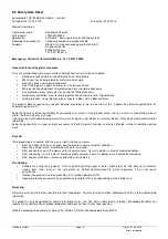
3.3.2 Alignment and installation
3.3.2.1 In general
The collectors should be aligned southward and show an ideal angle
according to latitude and application. The mounting frame can be
installed with different angles (30/45/60°). In addition, a variable angle
adjustment between 30 and 60° can be carried out on site.
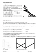
According the angle, the measures A and B (distance of mounting
points) change. The lengths A and B for different collectors and angles
are indicated in the chart below
:
Distances – vertical installation (mm)
Angle
A
B
C
D
E
F
G
H
I
J
30°
1840
1070
810
540
385
50
50
1825
o
r
1100
1000
or
2000
2000
45°
1500
1515
1070
655
60°
1065
1850
1515
920
Distances – horizontal installation (mm)
30°
1075
625
475
325
385
50
50
815
1600
1600
45°
875
880
625
385
60°
620
1085
880
550
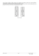
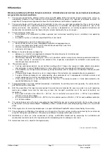
Fig. 9: Lateral view with hole center distances
3.3.2.2 Mounting procedure
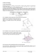
Define the angles of the collectors and install the mounting frame as depicted in fig 9, 10 and 11.
If the system is to be installed with another angle as foreseen, additional holes can be added. The distances of the holes must
then be calculated and measured. For roof angles smaller than 60°, the vertical angle section must be cut 25mm above the
hole.
Install the base of the frame, the cross bars and the back bars and connect the angle section according to fig. 10a. Bases’
screws should be fitted with the head on the side of the angle as shown in fig. 10b.
Define the leading edge of the mounting frame and mark the holes accordingly.
Distance of the carriers of the first mounting frame - vertical installation (I):
1000/2000mm
Distance of additional carriers - vertical installation (J):
2000 mm
Distance of the carriers of the first mounting frame - horizontal installation (I):
1600 mm
Distance of additional carriers – horizontal installation (F):
1600 mm
The holes of the vertical angle sections should be marked with the distance A in a right angle (use chalk line and angle). It is
also possible to mark the holes after the assembling of the mounting frame.
Put the mounting frame on the fixing points and tighten all screws.
The base must be connected and fixed with the surface.
The distance of the collectors from the surface should be about 20 cm to guarantee that collectors remain free from snow
during winter and that no dirt from the ground reaches the glass during strong rain.
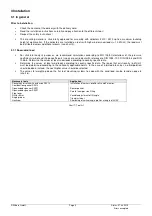
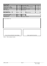
Fig. 10 : Base mounting
F
F
F
G
G
G
H
E
H
H
E
E
H
J
I
Fig 11 : Front view first mounting frame + extension


