© Wikora GmbH
Page 12
Status: 27.04.2015
Errors excepted.
4 Planning and layout data for collectors
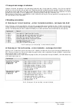
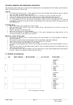
Recommendation:
System pressure
Primary pressure of expansion vessel
Flow rate
Switch-on temperature difference of controller
Switch-off temperature difference of controller
3,0 bar
2,5 bar
30 – 40l /m²/h
7 to 15 K *
3 to 8 K * (*internal to the plant)
Please note that for the layout of the collector circuit, the solar tube circuit and the heat exchanger circuit, the corresponding
pressure losses and the total pressure loss in combination with the desired flow rate must be considered.
Furthermore, please note that the calculation of the piping cross-sections must be carried out under the aspect of the
necessary flow velocity for solar installations from min. 0.4 m/s up to max. 1,5 m/s with the required flow rate liter/h.
Moreover, it must be considered that the hydraulic faulty wiring results in a system specific and demand specific flow rate which
involves a loss of pressure. This again has an influence on the layout of piping cross-sections, solar medium capacities, pump
pressures, flow-meter set-ups and flow-meter configurations as well as on their number.
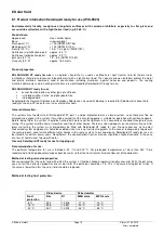
The values indicated in chart 9 apply only for pipe works up to an overall length of 30 m and heat exchangers with a capacity of
16 l.
Number of collectors
2
3
4
5
6
7
8
9
10
External diameter of the CU-connection pipe in mm
Flow rate in l/min*
Flow rate in l/h*
Expansion vessel in l
15
3
180
18
15
4,5
270
18
18
6
360
25
18
7,5
450
25
18
9
540
40
22
10,5
630
40
22
12
720
50
22
13,5
810
50
28
15
900
80
*Valid for parallel collector connection . In the case of series connection of the same collector arrays, the flow rate is halved.
Chart 9: Reference values for pipe work size, flow rates and diaphragm type expansion vessels.
Each solar system needs an adequate and competent planning and execution.
Please note that only a specialized
company is responsible for the layout of piping cross-sections, the layout of diaphragm type expansion vessel, the
determination of the solar pump group as well as the necessary flow-meter. Our data do not relieve of a special planning.
4.1 Hydraulic faulty wiring possibilities
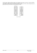
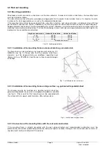
Our warranty covers the following configurations. Up to 6 collectors can be connected in parallel (see fig. 15). In case of an
installation in two lines, up to 3 collectors can be connected in series (see fig. 16). Please always ensure that all collectors are
connected uniformly and with a diagonal throughflow. A one-sided connection is not permitted. The connections between the
collectors must be realized with copper tubes of 18mm and an appropriate insulation. The collector fittings must be prepared
with the corresponding compression.
Crimp connections in the pipe work system are allowed. Seals must be approved for use in combination with solar systems and
temperatures up to 200°C. In case of a multiple-line installation, the return (cold water connection) should be located at the
collector line on the bottom.
Fig. 15: Installation in one line (4-5l / min.)
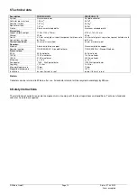
Fig. 18: Horizontal series installation according to Tichelmann
(4-5l / min.)
Fig. 16: Installation in two lines (4-5l / min.)
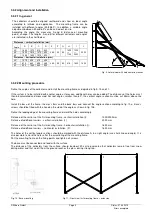
Fig. 17: Vertical
installation (4-5l / min.)


