


EN
14028755.03 02/2021 EN/DE/FR/ES
WIKA operating instructions model TGT73
19
8. Electrical connection
8. Electrical connection
The electrical connection of the transmitter is made through an angular
connector. The exact pin assignments can be found in the following
drawings. In addition, the pin assignment, output signal and the required
power supply are stated on the product label.
Explanation of the terminal assignments used:
U
B+
Positive terminal of the power supply
0 V
Negative terminal of the power supply
Sig+ Positive terminal of the output signal
Sig- Negative terminal of the output signal
The instruments must be connected to the equipotential bonding of the
plant.
Designation of terminal connectors
Terminals 1 and 2 are the connection terminals for the signal output
and the power supply, respectively. The terminal labelled PE (protective
earth) is internally connected to the casing. The connections 3 to 6 or
4 to 6 in the 3-wire variant, should be left free and must not be used as
points (see also chapter 3 "Specifications").
WARNING!
The gas-actuated thermometer with integrated rotary
encoder must be grounded through the thermometer
housing and through the ground terminal in the angular
connector.
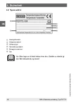
Summary of Contents for Intelli Therm TGT73.100
Page 24: ...EN 14028755 03 02 2021 EN DE FR ES 24 WIKA operating instructions model TGT73 ...
Page 46: ...DE 14028755 03 02 2021 EN DE FR ES 46 WIKA Betriebsanleitung Typ TGT73 ...
Page 68: ...FR 14028755 03 02 2021 EN DE FR ES 68 WIKA mode d emploi type TGT73 ...
Page 90: ...14028755 03 02 2021 EN DE FR ES 90 WIKA operating instructions model TGT73 ...
Page 91: ...14028755 03 02 2021 EN DE FR ES WIKA operating instructions model TGT73 91 ...


