background image

Weldmatic Fabricator

Operators Manual

10          

Model No. CP117-2, Iss C 05/07

Quality, Reliability, Performance

If the voltage is too low the wire will stub and 
stutter, and there will not be a steady arc. If 
the voltage is too high the arc will be long with  
metal transfer occurring as a series of large 
droplets. 

Important:

 Do not operate the Voltage 

Control switches during welding.

The weld setting should be chosen to suit the 
application and the thickness of the metal to 
be welded. It is important to check that the 
deposited weld provides sufficient strength to 
suit the application. 

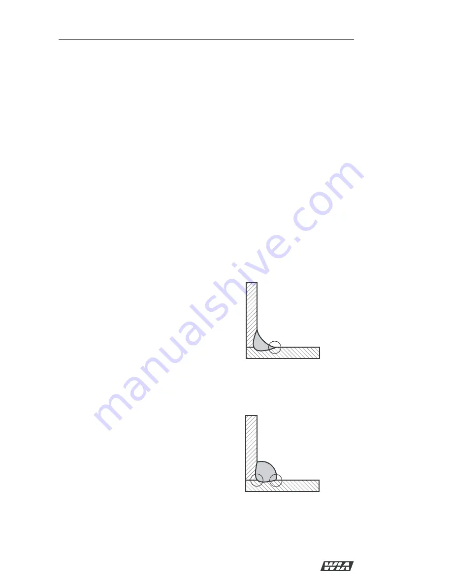
A “good” weld will have the characteristics 
illustrated in Figure 4. The weld has penetrated 
into the parent metal, fusing the root of the 
joint where the two plates meet, and the weld 
blends smoothly into the side walls.

A “bad” weld is shown in Figure 5. The weld 
has not penetrated the joint root, and there is 
poor side wall fusion. This lack of fusion would 
normally be corrected by increasing the arc 
voltage, or by increasing both wirefeed speed 
and arc voltage to achieve a higher current 
weld setting.

7 Basic Welding Information

Choice of Shielding Gas

The choice of shielding gas is largely 
determined by the consumable wire to be used. 
Many proprietary shielding gas mixtures are 
available.

The recommended shielding gases for use with 
the Weldmatic Fabricator are:

•  Mild Steel 

Argon +  
5 to 25% Carbon Dioxide; 
100% CO

2

•  Aluminium 

Argon;

•  Stainless Steel  Argon + 1 to 2% Oxygen.

Consult your gas supplier if more specific 
information is required.

Shielding Gas Flow Rate

In G.M.A. welding, one function of the 
shielding gas is to protect the molten weld pool 
from the effects of oxygen in the atmosphere. 
Without this protection the weld deposit 
becomes ‘honeycombed’ in appearance, an 
effect which is described as weld porosity.

In draft-free conditions the gas flow rate 
required to give adequate protection is 
typically 10-12 litres/min. In situations where 
drafts cannot be avoided, it may be necessary 
to increase this rate up to 20 litres/min, and/or 
to provide screening of the work area.

Weld porosity can also be caused by air 
entering the gas stream through a damaged 
hose, loose gas connection, or from restriction 
in the nozzle, such as from excess build-up of 
spatter.

When welding aluminium, particular care 
must be taken with all aspects of shielding gas 
delivery and workpiece preparation in order to 
avoid weld porosity.

Establishing a Weld Setting

Once the consumable wire type, wire size 
and shielding gas have been chosen, the two 
variables that are adjusted in order to obtain a 
the desired weld setting are;

•  Wirefeed speed,

•  Welding arc voltage.

The wirefeed speed determines the welding 
current; increasing the speed increases the 
current, and decreasing it decreases current. 

The selected wirefeed speed must be matched 
with sufficient arc voltage; a speed increase 
requires an increase of arc voltage.

Fig   “Good” Weld

Fig 5  “Bad” Weld

Summary of Contents for CP117-2

Page 1: ...dustries Ltd ABN 18 004 547 111 Telephone 1300 300 884 Facsimile 1300 301 884 Email Info welding com au www welding com au Weldmatic Fabricator external wirefeeder Operators Manual Weldmatic Fabricato...

Page 2: ...Weldmatic Fabricator Operators Manual Model No CP117 2 Iss C 05 07 Quality Reliability Performance...

Page 3: ...General Information Page Safe Practices 4 1 Introduction 6 2 Receiving 6 3 Specifications 6 4 Controls 7 5 Installation 8 6 Normal Welding Sequence 9 7 Basic Welding Information 10 8 General Maintenan...

Page 4: ...gas shielded arcs resemble acute sunburn but can be more severe and painful Wear protective clothing leather or heat resistant gloves hat and safety toe boots Button shirt collar and pocket flaps and...

Page 5: ...out of reach of sparks and heat or protect against ignition with suitable and snug fitting fire resistant covers or shields Walls touching combustibles on opposite sides should not be welded on or cut...

Page 6: ...s AUSTMIG ES6 is used with a shielding gas of Carbon Dioxide or Argon mixed with Carbon Dioxide Alternatively Flux cored consumable wires are available in both gas shielded and gasless self shielding...

Page 7: ...g voltage over ten steps 4 Positive Welding Output Terminal 5 Negative Welding Output Terminal 6 Gas Outlet Connector for shielding gas hose from remote wirefeeder 7 Wirefeeder Control Socket Connecto...

Page 8: ...ended mains circuit breaker rating for a Weldmatic Fabricator is 20 Amps Note Due to normal variations of sensitivity the tripping time of some 20A circuit breakers may limit the duty cycle available...

Page 9: ...act and to prevent gas leaks 6 Normal Welding Sequence Weld Start Closing the welding gun switch initiates this sequence of events The gas valve is energised and gas flow commences and continues for a...

Page 10: ...teel Argon 5 to 25 Carbon Dioxide 100 CO2 Aluminium Argon Stainless Steel Argon 1 to 2 Oxygen Consult your gas supplier if more specific information is required Shielding Gas Flow Rate In G M A weldin...

Page 11: ...conditions the equipment covers be removed and any accumulated dust be removed by the use of dry low pressure compressed air or a vacuum cleaner Wirefeed In order to obtain the most satisfactory weld...

Page 12: ...cable work clamp and gun cable assembly 2 Have primary supply circuit checked by a qualified electrician Circuit breaker trips when weld is started or during weld 1 Check the rating of the mains supp...

Page 13: ...Weldmatic Fabricator Operators Manual Model No CP117 2 Iss C 05 07 13 Quality Reliability Performance 10 Circuit Diagram Power Source Fig 7 Power Source Circuit Diagram...

Page 14: ...7 2 Iss C 05 07 Quality Reliability Performance Fig 8 Weldmatic Fabricator Power Source Assembly 11 Assembly and Parts List Weldmatic Fabricator Power Source 7 1 11 7 12 8 4 20 21 18 6 7 13 23 27 28 1...

Page 15: ...position 1 13 E0031 On Off Switch 1 14 CX58 Socket Dinse 2 15 TC265 5 8 UNF Nipple 1 16 TC266 5 8 UNF Nut 1 17 CP15 0 14 Control Socket 1 18 AM272 11N Digital Meter Assembly 1 19 D0024 Rectifier inclu...

Page 16: ...THEORY WHICH BUT FOR THIS PROVISION MIGHT ARISE BY IMPLICATION OPERATION OF LAW CUSTOM OF TRADE OR COURSE OF DEALING INCLUDING ANY IMPLIED WARRANTY OF MERCHANTABILITY OR FITNESS FOR PARTICULAR PURPOS...

Reviews: