PETS-2 Crossing Telephone System
QUICKFIX INSTALLATION HANDBOOK
Page 31
of 40
Issue 2
13/12/99
31
Note 1:
NC = Not Connected
Note 2:
Pairs 1 & 2 are paralleled to provide adequate current rating, both pairs must be
used.
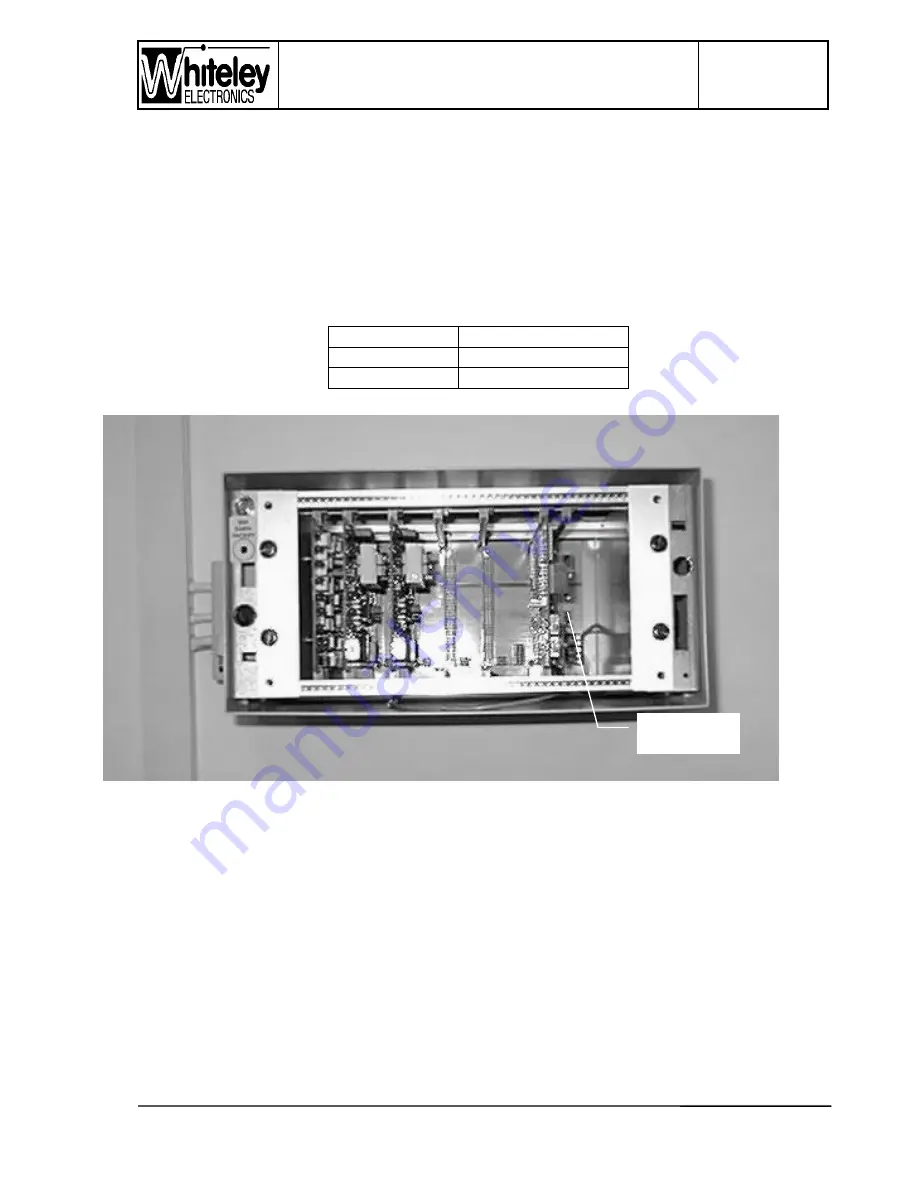
The Signal Box and Level Crossing Units are factory configured for 50V operation (to be
used with the PETS Power Supply & Battery Charger). Operation at 50V or 24V is
determined by a changeable link at the lower right hand side of the back-plane
motherboard, just above the screw terminals. The link is set as follows:
Link position
Voltage range (dc)
A-B
20V to 35V
B-C
35V to 58V
Figure 8 - Power Supply voltage selector (applicable to SB & LC Units)
The Alarm circuit is an opto-isolated input that may be used with a voltage in the range 20V
to 58V. When the input is powered, an alarm indication is raised. This input is intended for
use with the PETS Power Supply and Battery Charger, and wiring instructions will
accompany that unit since differences will be found between the original charger and the
new model.
Voltage range
selection link


