


PETS-2 Crossing Telephone System
QUICKFIX INSTALLATION HANDBOOK
Page 13
of 40
Issue 2
13/12/99
13
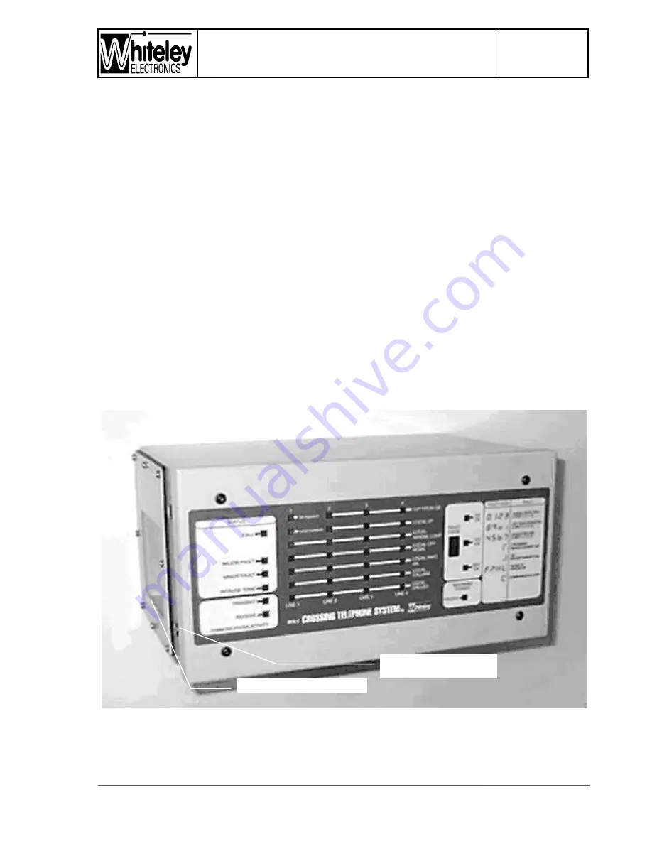
b) Line Identification window - Each Crossing will be geographically identified by a label to
be inserted from the top edge of the front panel, between the front Polyester membrane
and the aluminium panel. When the front panel is fitted it is not possible to access the
opening for this label, hence the label is securely located after installation. The black
PVC tape to the rear of the front panel is to prevent the LED’s behind from showing
through the paper insert labels. This is particularly relevant to Line 1, to prevent
illumination if a mains/ charger alarm occurs. When ‘Barrier Alarm signalling’ is required
on Line Cards 2, 3 or 4; puncture a hole in the PVC tape to selectively allow operation of
the required LED’s. In the photgraph the paper label inserts can be seen behind each
window.
c) Service Provider Identification window - an additional window is provided, with access
from the right hand edge of the front panel. This window will be used to identify the
Service Provider and fault notification telephone number.
Front panel layout is broken into functional sections, and the Fault Codes are identified with
a brief explanation to allow the Signaller to give a detailed indication of the fault status when
reporting problems. The INTERROGATE (a large lower case ‘i’ legend) button allows the
unit to be interrogated and the seven segment display to cycle through each alarm in the
event of multiple alarms. Other LED indicators are visible through the front panel, allowing
the general status of PETS 2 to be visible.
4.3 Level Crossing Unit
Figure 2 - Photograph of Level Crossing Unit
Item 3 - Frame retention
bolt & case earth point
Item 1 - Connection Plate


