background image

2-2

THE OVEN THERMOSTAT &

VENT MOTOR CAPACITOR

OVEN THERMOSTAT

The vent motor capacitor is located in the high
voltage area of the oven and is accessed by
removing the control panel. It is in use any time
the vent motor is in operation. The capacitor
helps to maintain a constant voltage to the vent
motor so that it runs smoother and more effi-
ciently.

The oven thermostat is located in the high volt-
age section of the oven and is accessed by
removing the control panel. The thermostat is
normally-closed and will open at a set tempera-
ture to disable the oven. The “trip” tempera-
ture is 194˚F (90˚C). The thermostat is
resettable.

VENT MOTOR CAPACITOR

FUSE 20A

POWER

TRANS

OVEN THERMOSTAT

3

1

L

N

RELAY 5

RELAY 7

VENT MOTOR

CAPACITOR

BK

BK

RD

BL

Summary of Contents for MH6140XKQ/B

Page 1: ...CONSUMER SERVICES TECHNICAL EDUCATION GROUP PRESENTS KM 27 JOB AID Part No 8178053 MICROWAVE OVEN HOOD COMBINATION ...

Page 2: ...fer to the Use and Care Guide or Tech Sheet provided with the microwave oven The Wiring Diagrams and Strip Circuits used in this Job Aid are typical and should be used for training purposes only Always use the Wiring Diagram supplied with the product when servicing the unit GOALS AND OBJECTIVES The goal of this Job Aid is to provide detailed information that will enable the service technician to p...

Page 3: ...1 Removing The Turntable Motor Cooktop Lamp Assembly 3 2 Removing The Control Panel Control Board 3 4 Removing The Door Switches 3 6 Removing The Oven Lamp Assembly 3 7 Removing The Oven Thermostat Line Fuse Power Cord 3 8 Removing The Vent Motor Capacitor The High Voltage Capacitor Rectifier 3 10 Removing The High Voltage Transformer 3 11 Removing The Magnetron 3 12 Removing The Vent Motor 3 13 R...

Page 4: ... iv NOTES ...

Page 5: ...ach meter leads with alligator clips when making operational tests For continued protection against radiation emission replace only with these types of switches Primary Interlock Switch SZM V16 FA 63 or VP 533A OF Secondary Interlock Switch SZM V01 FA 32 Interlock Monitor Switch SZM VI6 FA 62orVP 532A OF Oven Lamp Switch SZM V6 FA 31 or VP 331 A OD It is neither necessary nor advisable to attempt ...

Page 6: ...proceduresshould be exercised at all times Untrained personnel should not attempt service without a thorough review of test procedures and safety information con tained in this Job Aid WARNING TO SERVICE TECHNICIANS Whirlpool microwave ovens have a monitoring system designed to assure proper operation of the safety interlock systems The interlock monitor switch will immediately cause the oven fuse...

Page 7: ...ping or Abuse C Before turning on the microwave power for any service test or inspection within the microwavegeneratingcomponents check the magnetron wave guide or transmis sion line and cavity for proper alignment integrity and connections D Any defective or misadjusted components in the interlock monitor door seal and microwave generation and transmission systems shall be repaired replaced or ad...

Page 8: ...l normally register small emissions but they must be no greater than 4 mw cm2 to allow for measurement uncertainty NOTE Enter leakage readings in space BE FORE and AFTER on the service document All microwave ovens exceeding the emission level of 4 mw cm2 must be reported to Dept of Service for microwave ovens immediately and the owner should be told not to use the micro wave oven until it has been...

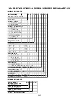
Page 9: ... 4 CU FT 10 1 0 CU FT 06 6 CU FT 12 1 2 CU FT 07 7 CU FT 14 1 4 CU FT 08 8 CU FT 15 1 5 CU FT 09 9 CU FT 16 1 6 CU FT FEATURE LEVEL 0 30 KIT IF KIT 2 22 KIT IF KIT 4 24 KIT IF KIT 5 SENSORED MODEL 7 27 KIT IF KIT FEATURE CODE C CSA APPROVED S CARRY IN WARRANTY EFFECTIVE 02 96 X IN HOME WARRANTY EFFECTIVE O2 96 YEAR OF INTRODUCTION J 2000 K 2001 L 2002 COLOR CODE B BLACK Q WHITE T BISCUIT ENGINEERI...

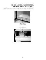
Page 10: ...1 6 MODEL SERIAL NUMBER LABEL AND TECH SHEET LOCATIONS The Model Serial Number label and Tech Sheet locations are shown below Model Serial Number Location Tech Sheet Location Behind Grille ...

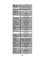
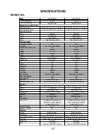
Page 11: ...t Scroll display Probe Temp Indication N A N A Weight Indication Lbs Lbs Clock Set ENTER TIME OF DAY ENTER TIME OF DAY Independent Minute Timer ENTER TIME IN MIN AND SEC ENTER TIME IN MIN AND SEC INTERIOR Size 19 7 8 W x 8 15 16 H x 14 5 32 D 19 7 8 W x 8 15 16 H x 14 5 32 D Capacity 1 4 Cubic Feet 1 4 Cubic Feet Finish Epoxy Powder Coat Epoxy Powder Coat Cooking Power 950 Watts 1EC 705 Rating 950...

Page 12: ...se Filter Yes 2 Yes 2 Charcoal Filter Yes 1 Yes 1 Blower Type Twin Squirrel Cage Twin Squirrel Cage Shipped Recirculating Mode Recirculating Mode OTHER SPECIFICATIONS Electrical 120V Single Phase 60 Hz 120V Single Phase 60 Hz 1500 Watts For Use With 1500 Watts For Use With 20 Amp Circuit 20 Amp Circuit Domestic Use Only Yes Yes Agency Approvals FCC DHHS U L Listed FCC DHHS U L Listed Approx Shippi...

Page 13: ...ents of 10 Scale Digital Levels Ten 10 Operation Direct Entry Ventilation Forced Air Exhaust Fan Yes High Yes 220 CFM Vertical Low Yes 110 CFM Vertical Manual Off Yes Auto Off No Auto On Yes 56 degrees C Cooktop Light Yes One 1 On Yes 30 Watts Night Yes 17 Watts Manual Off Yes INTERIOR Size 19 7 8 W x 8 15 16 H x 14 3 16 D Capacity 1 4 Cubic Feet Finish Epoxy Powder Coat Cooking Power 950 Watts 1E...

Page 14: ...Damper Yes Grease Filter Yes 2 Charcoal Filter Yes 1 Blower Type Twin squirrel cage Shipped Recirculating Mode OTHER SPECIFICATIONS 120V Single Phase 60 Hz 1500 Watts For Use With 20 Amp Circuit Domestic Use Only Yes Agency Approvals FCC DHHS U L Listed Approx Shipping Weight 58 lbs Approx Net Weight 52 lbs LITERATURE Use Care Guide Whpl 8183914 3828W5A1906 English Cooking Guide Whpl 8183915 3850W...

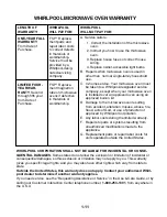
Page 15: ...e ment parts and repair labor costs to correct defects in materials or workmanship Service must be provided by a Whirlpool desig nated servicing company FSP Replace ment magnetron tube on microwave ovens if defective in materials or workmanship A Service calls to 1 Correct the installation of the microwave oven 2 Instruct you how to use the microwave oven 3 Replace house fuses or correct house wir...

Page 16: ...1 12 NOTES ...

Page 17: ...OUNTING POSITIONS RECIRCULATING AIR REAR VENTED AIR AIRFLOW TOWARDS FRONT OF UNIT AIRFLOW TOWARDS REAR OF UNIT AIRFLOW TOWARDS TOP OF UNIT TOP VENTED AIR NOTE All microwave ovens are shipped with the vent motor in the Top Vented Air position ...

Page 18: ...constant voltage to the vent motor so that it runs smoother and more effi ciently The oven thermostat is located in the high volt age section of the oven and is accessed by removing the control panel The thermostat is normally closed and will open at a set tempera ture to disable the oven The trip tempera ture is 194 F 90 C The thermostat is resettable VENT MOTOR CAPACITOR FUSE 20A POWER TRANS OVE...

Page 19: ...ough outside vent ing or by recirculation The turntable motor is a synchronous motor that turns the food so that microwave energy entering it is evenly distributed during cook ing FUSE 20A OVEN THERMOSTAT RD BK BK RELAY5 RELAY3 L N WH WH SECONDARY INTERLOCK SWITCH RELAY 7 RELAY 7 BK 7 5 OL HIGH VOLTAGE SECTION VENT MOTOR TURNTABLE MOTOR ...

Page 20: ...2 4 NOTES ...

Page 21: ... Microwave Oven Hood Combination The components and their locations are shown below Vent Motor Cooktop Lamp Turntable Motor Primary Interlock Switch High Voltage Rectifier High Voltage Capacitor Line Fuse Magnetron High Voltage Transformer Oven Lamp Oven Thermostat Vent Motor Capacitor Monitor Switch Secondary Interlock Switch ...

Page 22: ...wer the top edge of the cover so you can access the compo nent wiring below it 3 Lower the bottom cover as far as possible Bottom Cover Screw 1 of 7 Turntable Motor Connector ELECTRICAL SHOCK HAZARD Disconnect power before servicing Replace all panels before operating Failure to do so could result in death or electrical shock WARNING 4 To remove the turntable motor a Remove the glass turntable rol...

Page 23: ...h the cover slots then remove the lamp assembly b Remove the bulb from the socket Cooktop Lamp Socket NOTE When you reinstall the bottom cover place the edge below the five tabs as shown below Unlock Lock Tabs Bottom Cover Turntable Motor Screw 1 of 2 c Remove the two screws from the turn table motor and remove the motor ...

Page 24: ...r screws from the top of the cabinet 3 Pull the top of the air grille forward lift the bottom tabs from the slots and remove the grille from the microwave oven Air Grille Screws 4 Open the microwave oven door 6 Disconnect the 2 and 11 pin connectors from the control board and remove the control panel assembly Control Panel Screw 2 Pin Connector 11 Pin Connector Control Panel Control Panel Assembly...

Page 25: ...lift the rail then pull the end of the ribbon cable out of the connector Ground Wire Screw Locking Rail 8 Remove the green ground wire screw from the control panel Transformer Bracket Screws 10 Press the locking tab and unlock it from the end of the control board then pull the other end of the board out of the holder slots and remove the board ...

Page 26: ...itch a Disconnect the wire connectors from the terminals b Carefully push in on the locking arm be careful not to break it off while you twist the switch on the pivot pin and remove the switch from the bracket NOTE If a locking arm breaks you will have to replace the entire bracket so be careful when bending the arms 2 White Wires 2 White Wires 1 Large 1 Small Raise Locking Arm Pull Out Here ELECT...

Page 27: ...lle from the microwave oven Air Grille Screws 5 Facing the rear of the socket turn it coun terclockwise and align the socket locking tabs with the bracket slots and remove the socket 4 Lift the oven lamp mounting bracket by its tab and remove the lamp assembly from the mounting location NOTE Be careful not to break the fragile wire socket con nectors Lift Tab Lamp Mounting Bracket 6 Remove the bul...

Page 28: ...ontrol panel opening 5 To remove the line fuse a Open the fuseholder b Pull the clips off the ends of the 20A line fuse and remove the fuse from the fuseholder Clip Clip 20A Fuse ELECTRICAL SHOCK HAZARD Disconnect power before servicing Replace all panels before operating Failure to do so could result in death or electrical shock WARNING Power Cord Oven Thermostat Line Fuse Oven Thermostat 4 To re...

Page 29: ...se b Remove the green ground wire screw c Remove the white wire connector from the oven thermostat terminal Black Wire To Line Fuse Green Ground Wire Screw Pull Power Cord Out Of Air Duct d Slide the power cord out of the air duct holder slots White Wire Connector To Oven Thermostat ...

Page 30: ... careful 6 Splice the wires on the new capacitor to the old capacitor wires 7 To remove the high voltage capacitor and high voltage rectifier a Disconnect the wires and rectifier lead from the terminals of the high voltage capacitor b Remove the mounting screw from the clamp and remove the rectifier and capacitor Vent Motor Capacitor 5 To remove the vent motor capacitor a Cut the wires near the bo...

Page 31: ...age capacitor with a 20 000 Ω resistor to chassis ground 5 Remove the high voltage capacitor and high voltage rectifier see page 3 10 for the procedure HV Transformer 6 Disconnect the white and black wires from thetwoterminalsonthehighvoltagetrans former 7 Disconnect the 3 wire connector from the magnetron Black White 3 Wire Connector 8 Remove the four screws from the high voltage transformer belo...

Page 32: ...ing Replace all panels before operating Failure to do so could result in death or electrical shock WARNING 1 Disconnect the electrical power to the microwave oven 2 Remove the control panel from the micro wave oven see page 3 4 for the proce dure 3 Remove the high voltage access panel from over the control panel opening see page 3 8 step 3 4 CAUTION Discharge the high voltage capacitor with a 20 0...

Page 33: ...arefulwhenhandlingthesheetmetal parts Sharp edges may be present and you can cut yourself if you are not careful WARNING 3 Remove the microwave oven from its mounting location 4 Remove the three screws from the air vent cover on the top of the cabinet and remove the cover Roller Assembly Glass Turntable 5 Remove the vent motor mounting screw from the rear panel 6 Lift the vent motor out of the ope...

Page 34: ...rewdriver 3 To remove the oven door a Lift the door and remove the bottom hinge pin from its bracket hole then lower the door and remove the top hinge pin from its bracket hole b Use a putty knife and pry out along the inner edge of the choke cover c Pull out on the cover to release all of the locking tabs and remove the cover from the door Pull Out Pry Out Along Inner Edge With Putty Knife b Plac...

Page 35: ... the bottom and right sides of the inner door frame while you lift the frame c When the inner door frame is free of the tabs slide the frame out of the 3 top holders and remove it e Unhook the actuators from the slots in the inner door frame Door Frame Screw 1 of 2 Inner Door Frame Unclip 3 Tabs Start Here Slide Out Of Holders Unclip 3 Tabs Unhook Spring Switch Actuators Hook Hook Continued on the...

Page 36: ...he outer glass a Use a screwdriver and push the 10 locking tabs see the arrows below back so they are not over the glass Outer Glass b Lift the glass and remove it from the door frame Tab Pushed Back Tab Over Outer Glass ...

Page 37: ...ntact with the contact areas on the ribbon cable TOUCH PANEL CONTINUITY MH6140XK 6141XK MHE14XK Flex Circuit Connector Before testing any of the components perform the following checks Disconnect the power supply cord from the outlet before removing the outer cabinet from the unit Discharge the high voltage capacitor and removethewiresfromtheprimarywindingof thehighvoltagetransformerbeforeconduct ...

Page 38: ...ower to the microwave oven 2 Disconnect the vent motor wires from the control board 3 Set the ohmmeter to the R x 1 scale 4 Touch the ohmmeter leads to the indi cated vent motor power plug wire connec tors The meter should indicate the follow ing readings Black to white Low 115 to 125 Ω Blue to black High 60 to 75 Ω VENT MOTOR TURNTABLE MOTOR ELECTRICAL SHOCK HAZARD Disconnect power before servici...

Page 39: ...m the termi nals b Touch the ohmmeter leads to the ter minals c When the thermostat is open opens 194 F 90 C the meter will indi cate infinity across the terminals d When the thermostat is closed the meter will indicate continuity 6 To test the door switches a Disconnect the wires from the termi nals b Touch the ohmmeter leads to the ter minals of the primary or secondary interlock switches normal...

Page 40: ... at both terminals THE HIGH VOLTAGE CAPACITOR RECTIFIER DIODE High Voltage Capacitor High Voltage Rectifier HV Transformer wht Rectifier Magnetron Filament red blk Anode Cathode ELECTRICAL SHOCK HAZARD Disconnect power before servicing Replace all panels before operating Failure to do so could result in death or electrical shock WARNING 4 To test the high voltage rectifier a Set the ohmmeter to th...

Page 41: ...nd lug The meter should indicate between 65 and 120 Ω 6 Touch the ohmmeter leads to the two red blackfilamentterminals Themetershould indicate 0 Ω 7 Set the ohmmeter to the R x 1K scale 8 Touch one ohmmeter lead to the trans formerchassisgroundlug Touchtheother lead to each of the filament terminals The metershouldindicateinfinityatbothtermi nals THE HIGH VOLTAGE TRANSFORMER Black White Red Black ...

Page 42: ... terminals The meter should indicate less than 1 Ω 5 Set the ohmmeter to the R x 1K scale 6 Touch one ohmmeter lead to the magne tron case Touch the other lead to each of the filament terminals The meter should indicate infinity at both terminals THE MAGNETRON Magnetron Filament Terminals Filament Terminals ELECTRICAL SHOCK HAZARD Disconnect power before servicing Replace all panels before operati...

Page 43: ...Y INTERLOCK SWITCH TOP SECONDARY INTERLOCK SWITCH BOTTOM H V CAPACITOR RECTIFIER 1 DOOR OPENED COOK OFF MODE NOTE THERMISTOR MONITOR SWITCH MIDDLE H V TRANSFORMER MAGNETRON GND OVEN LAMP L V TRANSFORMER FUSE 20A MICROCOMPUTER BOARD 120 VAC 60 HZ SINGLE PHASE ONLY OVEN THERMOSTAT 90 C 194 F ...

Page 44: ...RMOSTAT WH BK 3 1 RELAY 7 FUSE 20A POWER TRANS OVEN THERMOSTAT 3 1 BK RD WH WH BK L N BR BK RELAY 3 WH BL OVEN LAMP O L 5 RELAY 7 FUSE 20A POWER TRANS OVEN THERMOSTAT BK RD WH WH BK 3 1 L N PK RELAY 5 BL VENT MOTOR LOW V M 7 RELAY 7 FUSE 20A POWER TRANS OVEN THERMOSTAT BK RD WH WH BK 3 1 L N BK RELAY 4 BL VENT MOTOR HI V M 6 RELAY 7 FUSE 20A POWER TRANS OVEN THERMOSTAT BK RD BK 3 1 L N BK RELAY4 B...

Page 45: ...N WH WH WH BR RELAY 3 YL WH SECONDARY INTERLOCK SWITCH TURNTABLE MOTOR T M 5 FUSE 20A POWER TRANS OVEN THERMOSTAT BK RD BK 3 1 N WH WH BL RELAY1 RELAY 2 WH COOKTOP LAMP CL 4 RELAY 7 L FUSE 20A OVEN THERMOSTAT POWER TRANS RD BK BK RELAY 5 RELAY 3 L N WH WH WH SECONDARY INTERLOCK SWITCH RELAY 7 RELAY 7 BK V M 7 1 3 5 OL T M HIGH VOLTAGE SECTION ...

Page 46: ...5 4 NOTES ...

Page 47: ...R READY TO IDENTIFY YOU AS AN AUTHORIZED SERVICER FOR LITERATURE ORDERS PHONE 1 800 851 4605 IN CANADA FOR PRODUCT SPECIFICATIONS AND WARRANTY INFORMATION CALL 1 800 461 5681 FOR TECHNICAL ASSISTANCE WHILE AT THE CUSTOMER S HOME CALL THE TECHNICAL ASSISTANCE LINE 1 800 488 4791 HAVE YOUR STORE NUMBER READY TO IDENTIFY YOU AS AN AUTHORIZED SERVICER FOR WHIRLPOOL PRODUCTS 1 800 253 1301 FOR KITCHENA...

Page 48: ...CORPORATION ...
Reviews: