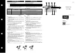
TABL E 2
D I R ECTIONAL U N I T CALI B
Relay Rati ng
Current
Adjust
Adjustment
Check Points ¢
. 5-2 Amp
25 Amp
Core
t t
Rotate core b y m eans o f adjuster
1 5
&
5 Amp s .
1 -4 Amp
lo cated on bottom side of
2-8 Amp
cylinder unit. Adjust core so
that a slight contact opening
torque is mad e .
4- 1 6 A m p
50 Amp
30
&
1 0 Amp s
1 0-40 Amp
75 Amp
45
&
15 Amps
20-80 Amp
. 5-2 Amp
50 Amp
If spurious torque is in the
40, 25
&
10 Amps
1 -4 Amp
contact closing direction
2-8 Amp
(l eft front view) screw out
right magn etic plug until
direction o f spurious torque
Magnetic
is reversed.
Plugs
If spurious torque i s i n the
contact opening direction, screw
out left plu g u ntil spurious
4-16 Amp
100 Amp
torque is s light contact op ening.
80, 50
&
20 Amp s
1 0-40 Amp
1 50 Amp
1 20 , 75
&
30 Amps
2 0-80 Amp
t
Short circuit the voltage polarizi n g circuit at the relay terminal s b efore making th e abo v e adj ustments.
t t
Plugs should be at fully in po sition prior to adjust ment of core.
¢ There s hould be no closing t o rque at these points. Any t endency for the contact to pickup at these points m ay
be revers ed by slight readju st ment of the c ore or p lugs.
1 1
www
. ElectricalPartManuals
. com
Summary of Contents for KRD-4
Page 27: ...w w w E l e c t r i c a l P a r t M a n u a l s c o m ...
Page 108: ... w w w E l e c t r i c a l P a r t M a n u a l s c o m ...
Page 110: ...w w w E l e c t r i c a l P a r t M a n u a l s c o m ...
Page 112: ...w w w E l e c t r i c a l P a r t M a n u a l s c o m ...
Page 114: ...w w w E l e c t r i c a l P a r t M a n u a l s c o m ...


