background image


Noran  Tel     


Page 5 of 16


a subsidiary of Westell, Inc


1

Communication Settings Menu (1) 


When a user types 1 and presses the <enter> 
key Figure 1-1  “Communication Settings 
Menu” is displayed. 
 
This menu provides submenus for configuring 
communication options for the Site Vu. 


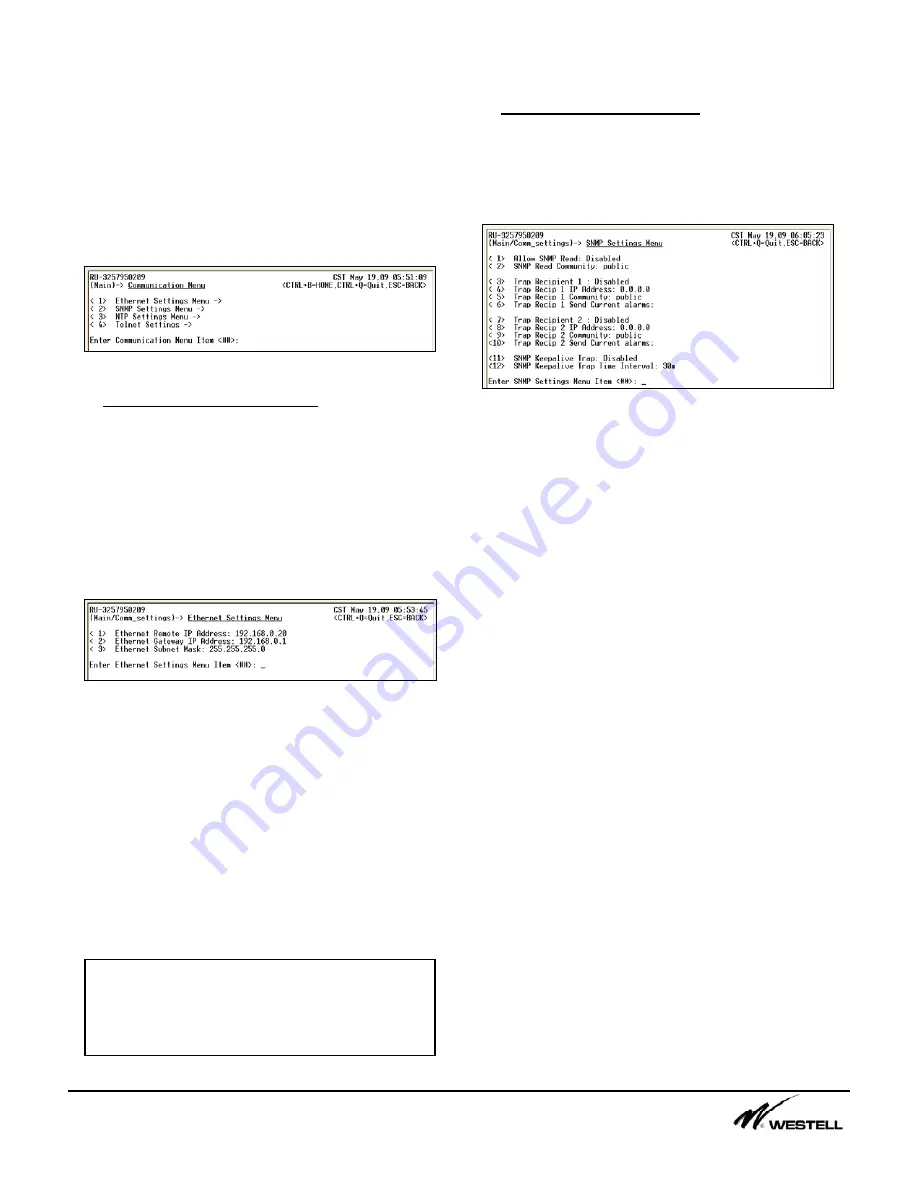
Figure 1-1  Communications Settings Menu


1.1  Ethernet Settings Menu (1) 
This submenu allows a user to configure the 
SiteVu remote unit for operation on a network.  
Figure 1-2 displays the options that may be 
changed on this submenu.  These menu items 
must be configured to communicate to the 
remote unit over Telnet, to have the remote unit 
send SNMP traps, and to have the remote unit 
communicate to a time server. 


Figure 1-2  Ethernet Settings Menu


The Ethernet Remote IP address is a statically 
assigned IP address for the Site Vu connected 
on the local area network. 
 
The Ethernet Gateway IP address is the IP 
address for the gateway on the local area 
network that the Site Vu is connected to.   
 
The Ethernet Subnet Mask is the network mask 
for the Site Vu connected to the local area 
network. 


1.2  SNMP Settings Menu (2) 
This menu allows the user to configure the 
SiteVu remote unit to send SNMP v1 traps to 
Network Management Station(s).  Figure 1-3 
displays the menu item settings for this menu. 


Figure 1-3  SNMP Settings Menu


The Allow SNMP Read menu item can be 
enabled to allow a user to view the SiteVu’s 
information via a SNMP Network Management 
Station (NMS). 
 
The SNMP Read Community menu item is the 
keyword required at the NMS to view the Site 
Vu through the NMS software.  
 
The Site Vu can send events to two SNMP 
Trap recipients.  A recipient must be enabled in 
order for the Site Vu to send traps.  An IP 
address must be setup for each recipient.  The 
community string is the keyword that the 
associated trap monitor uses.  “Send Current 
Alarms” allows the user to force any current 
alarms out to the SNMP trap manager. 
 
The SNMP Keepalive Trap menu item can be 
enabled so the remote unit will send out a trap 
to the configured recipients.  This trap contains 
the remote unit’s name (syslocation) and the 
current alarm counts for each severity Level.   
 
The user can define the time interval between 5 
minutes and 32,727 minutes (22 days 18 hours 
7 minutes).  The user can enter a time directly 
in minutes (e.g. “300”) or qualify it in days (d), 
hours (h) and minutes (m) (e.g. “1d 10h 50 m”) 

Note: 

These menu items can NOT be 

changed when using a Telnet session.  They 
can only be configured when using the 
Service Port on the Site Vu remote unit. 

Summary of Contents for Noran Tel SITE VU MINI N04005-SVU/L0806

Page 1: ...emote units using the local port service port via USB and or using the Telnet option over Ethernet Any VT100 compatible Telnet client software and serial communication software may be used to communic...

Page 2: ...n is dropped The user must wait a set amount of time Security Lock Out time before trying to reconnect via Telnet After a successful login the Site Vu Main Menu is displayed If 3 failed logins occur f...

Page 3: ...5 DIGITAL OUTPUTS 5 9 6 CURRENT ALARMS 6 9 7 SECURITY 7 10 7 1 USER PROPERTIES MENU 1 5 10 7 2 SECURITY LOG MENU 6 10 7 3 ACCESS CONTROL LIST MENU 7 11 7 4 SECURITY LOCKOUT MENU ITEMS 8 10 11 8 FILE T...

Page 4: ...item that contains a colon and presses the Enter key the menu item selected is displayed along with its previous setting Also a prompt is displayed for the user to enter a new value for the setting Th...

Page 5: ...nit to send SNMP v1 traps to Network Management Station s Figure 1 3 displays the menu item settings for this menu Figure 1 3 SNMP Settings Menu The Allow SNMP Read menu item can be enabled to allow a...

Page 6: ...ge the default port for the Telnet server A user may want to change this port for access through firewalls and or to obfuscate the location of the Telnet server on the SiteVu remote unit The Telnet In...

Page 7: ...to add a de bounce time to eliminate jitter on the sensor This value can be anywhere between 1 10th of a second to 6553 1 seconds 109 minutes Refer to the Digital Input sensor section in the hardware...

Page 8: ...outputs a voltage between 0 50mV Rather than displaying a voltage and using alarm points in the mV range the value can be converted to Amperes instead o Multiplier 400A 50mV 8000 o Range 0 125mV o Of...

Page 9: ...ensor is controlled by an alarm event When AUTO is set the state of the relay SET or CLEAR is displayed after the AUTO setting When the digital output changes state a SNMP trap is automatically sent a...

Page 10: ...ACCESS READ ACCESS or READ WRITE ACCESS The read privilege allows that user to view all the menus in that section The read and write access privilege allows a user to read the menus and change the con...

Page 11: ...hat are currently locked Also a failed login Security Log item is created in the Security log menu item A username becomes locked if the user tries to login with the correct username but not the corre...

Page 12: ...tings 6 The firmware in the SiteVu can be updated remotely using the menu options available in Figure 8 3 Figure 8 3 Firmware File Settings Menu The Enable File Transfer menu item allows the user to e...

Page 13: ...cessed through this menu Figure 10 1 System Properties Menu The Current time item allows a user to set the time for the remote unit The time entered is based on the Time Zone offset from UTC menu item...

Page 14: ...t regular intervals and store the results in a tab separated value file tsv Initially data is logged every second After the first 5 minutes it is logged less frequently at 1 minute intervals The Site...

Page 15: ...puts it on the user s computer The first two steps essentially copies the configuration from one SiteVu remote unit and places that same configuration on the second remote unit Downloading with XMODE...

Page 16: ...tput Number Low 11 Output State on Alarm Low 12 High Alarm enable 13 Send SNMP Trap High 14 High Alarm Point 15 Return Point High 16 Severity High 17 Digital Output Number High 18 Output State on Alar...

Reviews: