


43
3. Click on
Edit
near the bottom of the window.
4. Create a new covered area if there are none present.
CAUTION
The covered area name will appear in the upper left corner of the
Connex CS display screen. Always refer to the
Connex CS Customer Project
Req Form, Appendix B2
when entering information in these fields.
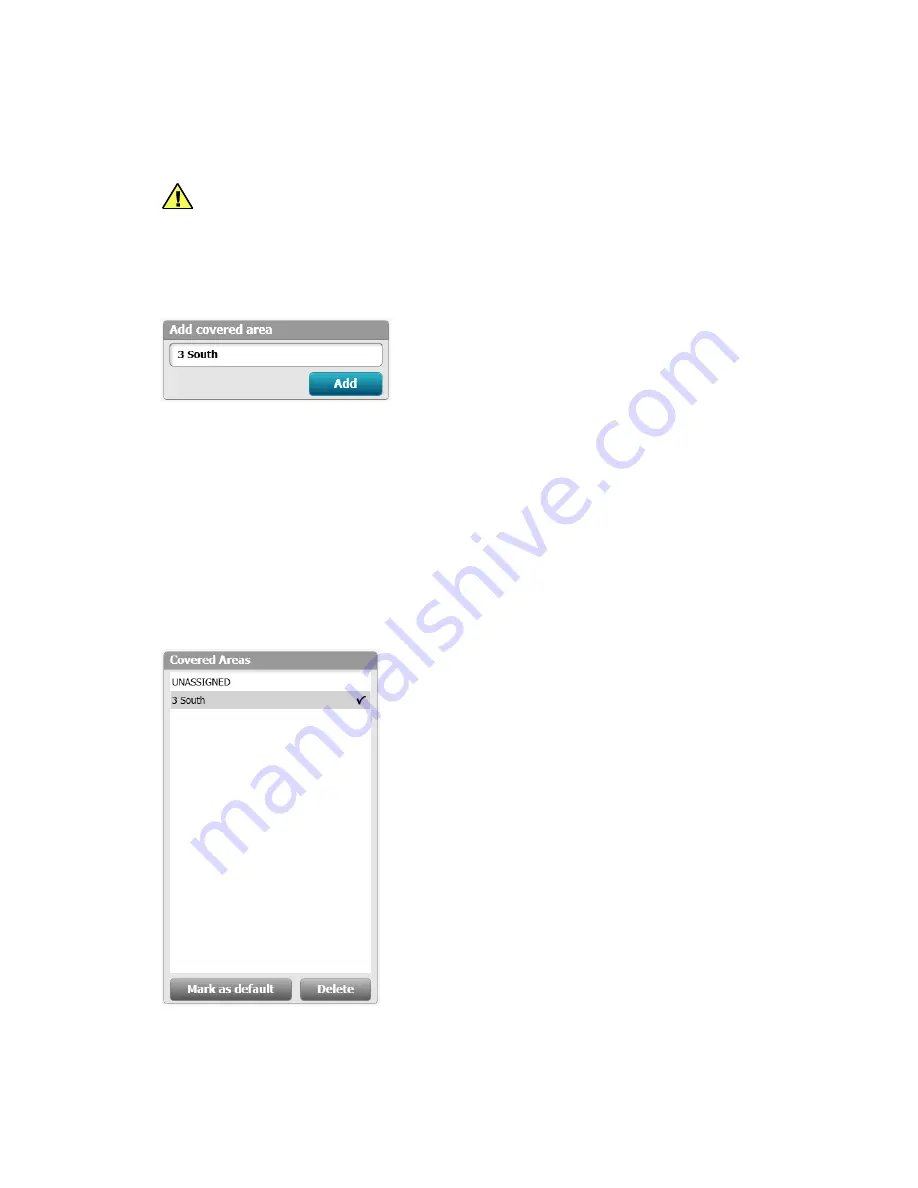
5. Click in the
Enter new covered area
field and enter the covered area name. An example is
shown in
“Figure B-15: Add covered area example”.
Figure B-15: Add covered area example
6. Click
Add
when finished. The newly create covered area appears above in the Covered
areas window by name.
7. Click on the new covered area, 3 South in this example, and click on
Mark as default
if this is
the default system for the network. See
“Figure B-16: Covered areas window example” for an
example.
Note
The default covered area provides a setting for all new devices to connect to the
network for the first time, prior to being assigned to a location. There can be only
one default covered area for a network. For a stand-alone central station, where
there is only a single covered area, always mark the covered area as default.
Figure B-16: Covered areas window example
8. Observe the hierarchy within the
Assign beds to covered area window
to the right, click on
the
expander
arrow next to the previously configured facility name.
9. Keep expanding all layers until the previously configured rooms and beds are viewable.
Summary of Contents for Connex CS
Page 1: ...Welch Allyn Connex CS Central Station Install Guide Platform CPU...
Page 13: ...7...
Page 19: ...13...
Page 23: ...17...
Page 29: ...23...
Page 33: ...27...
Page 35: ...29...
Page 43: ...37 Figure B 9 Newly added Room and Bed examples...
Page 65: ...59 Figure B 29 View configuration with multiple views created example...
Page 80: ...74 Configuration Details and an alarm condition occurs...
Page 89: ...83...
Page 97: ...91...
Page 99: ...93 Figure D 1 Shell Mode configuration screen example...
Page 103: ...97...
Page 112: ...106 Repeater Display Install Figure E 6 Shell Mode configuration screen example...
Page 120: ...114 Repeater Display Install Figure E 18 Shell Mode configuration screen example...
Page 121: ...115...
Page 133: ...127...


