background image

上海维宏电子科技股份有限公司


Weihong Electronic Technology Co., Ltd. 

-  72  -                                                                                                                                Specialized,  Concentrated,  Focused 


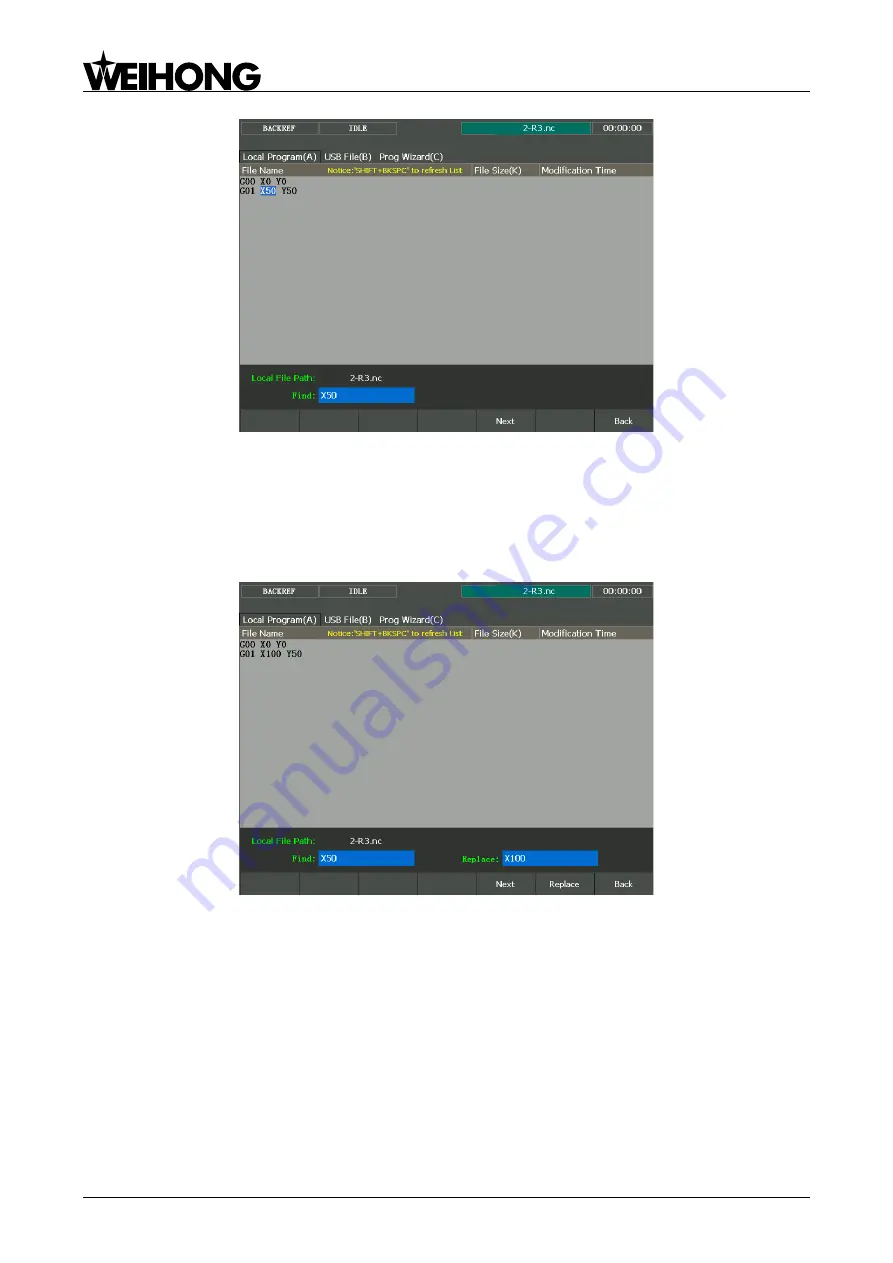
Fig. 3-48 Find page 

If you want to replace a certain program block, you can 

press F5 ―Replace‖. Enter the find content 

and 

replace content, and then press ―Enter‖. In the replace page, press F6 ―Replace‖ to replace the find 

content with the replace content, and then pre

ss F5 ―Next‖ to find the next place, and then press F6 to 

execute replacement. You can continue this process until all the find content are replaced by the replace 

content

, or press F7 ―Back‖ to go back. See Fig. 3-49. 


Fig. 3-49 Replace page 

If you want to clear the contents in the edit page, you can press F6 ―Clear Contents‖.   


Unload and Copy to USB 

Pressing  shortcut  key  F2  will  unload  the  file  currently  being  processed,  corresponding  to  the 

operation of ―Load‖. 

Pressing shortcut key F6 (the premise is that a removable disk has already been inserted) will copy 

the file selected to the removable disk. 

Press letter key B to enter [USB File (B)] screen, as shown in Fig. 3-50, in which files in the USB 

flash disk can be read in. Users can also do the following operations to them, like ―Load‖, ―unload‖, ―Edit‖, 
―Delete‖, ―New‖, ―Rename‖, and ―Copy to local‖. Folders can be opened by pressing ―Enter‖. 

Summary of Contents for NK280

Page 1: ...NK280 Integrated CNC System Manufacturers Manual 2nd Edition Weihong Electronic Technology Co Ltd ...

Page 2: ...ontained in this manual may not be reproduced transferred or translated without any prior written permission of Weihong Company The information contained in this manual is constantly being updated You can login to the official website of Weihong Company http en weihong com cn to download the latest PDF edition for free Second Edition February 2016 XXX Printing XX XXXX 158 pages ...

Page 3: ...ter 5 talks about maintenance information so that users can take corresponding steps in case of breakdown 5 Appendix part including chapter 7 and 8 Chapter 7 lists all the parameters while chapter 8 contains the software license agreement Applicable Product Models This manual is applicable to NK280 integrated CNC system Refer to the table below for details Product Model Remarks NK280 integrated CN...

Page 4: ... degree of loss or injury in case of negligence or omission of precautions stipulated in this manual CAUTION general info mainly for informing such as supplementary instructions and conditions to enable a function In case of negligence or omission of this kind of precautions you may not activate a function Note that in some circumstances negligence or omission of even this kind of precautions coul...

Page 5: ... the cabinet wall for plugging cable connected with the device and the ventilation heat dissipation in the cabinet Space between this device and other equipments should also be preserved according to the requirements The product should be installed firmly and without vibration During installing casting knocking striking or loading on the product is forbidden To reduce electromagnetic interference ...

Page 6: ...lowed to frequently power on and power off It is recommended to power up the machine again at least one 1 minute later after power failure or blackout CAUTION 1 Precautions Related to Product and Manual Matters related to restrictions and functions available stipulated in the manuals issued by the machine manufacturer is prior to those in this manual This manual assumes adding all optional functio...

Page 7: ... System 21 2 2 2 2 Dual Z System 22 2 3 PORT DEFINITION AND WIRING SPECIFICATION 24 2 3 1 Driver Interface Definition 24 2 3 2 Handwheel Interface Definition 26 3 MANIPULATION 27 3 1 DEBUGGING STEPS 29 3 2 ADJUSTMENT OF AXIAL DIRECTION AND PULSE EQUIVALENT 30 3 2 1 Axial Direction Adjustment 30 3 2 2 Pulse Equivalent Adjustment 30 3 2 3 Upper Lower Limit Setting of Workbench Stroke 32 3 3 RETURNIN...

Page 8: ... Program Wizard 68 3 13 2 Part Statistic 69 3 13 3 Program File 69 3 14 HANDWHEEL OPERATION 75 3 14 1 Handwheel Mode 75 3 14 2 Handwheel Guide 75 3 15 SYSTEM MANAGEMENT 77 3 15 1 System Info 77 3 15 2 Network Connection 77 3 15 3 Language 77 3 15 4 Register 77 3 16 NETWORK CONNECTION AND SHARE 79 3 16 1 IP Setup 79 3 16 1 1 Direct Connection or Switch Connection 79 3 16 1 2 Router Connection 82 3 ...

Page 9: ...107 6 1 DRIVER PARAMETERS 108 6 1 1 Parameter Setting of WISE Servo Driver 108 6 1 2 Parameter Setting of YASKAWA Σ Ⅱ Servo Driver 109 6 1 3 Parameter Setting of YASKAWA Σ Ⅴ Σ 7 Servo Driver 111 6 1 4 Parameter Setting of PANASONIC MINAS A4 Servo Driver 112 6 1 5 Parameter Setting of PANASONIC MINAS A5 Servo Driver 113 6 1 6 Parameter Setting of MITSUBISHI MR JE Servo Driver 115 6 1 7 Parameter Se...

Page 10: ...ISHI MR E Servo Driver 138 6 3 6 Wiring Diagram of DELTA Servo Driver 138 6 3 7 Wiring Diagram of FUJI Servo Driver 141 6 3 8 Wiring Diagram of HITACHI Servo Driver 141 6 3 9 Wiring Diagram of SANYO PY Servo Driver 142 6 3 10 Wiring Diagram of SANYO R Servo Driver 142 6 3 11 Wiring Diagram of KT270 Servo Driver 143 6 3 12 Wiring Diagram of STONE GS Servo Driver 143 6 3 13 Wiring Diagram of TECO TS...

Page 11: ...d Specialized Concentrated Focused 5 1 Summarization 1 1 HARDWARE INTRODUCTION 6 1 1 1 A Picture of NK280 6 1 1 2 System configuration 6 1 1 3 Mounting Dimension 6 1 1 4 Host of NK280 7 1 1 5 Connection Schematic Diagram 11 1 2 SOFTWARE INTRODUCTION 12 ...

Page 12: ... cable length custom Servo cable brand length and quantity decided by customers NK MPG 06 Handwheel optional Note The above lists the system components of standard configuration and the final receiving should be subject to the receipt list The extended terminal board EX26A is optional 1 1 3 Mounting Dimension After NK280 is installed on the machine tool 100 mm space should be preserved in its surr...

Page 13: ...4 362 Fig 1 2 Mounting dimension of NK280 integrated system 1 1 4 Host of NK280 Front View of NK280 E stop Button Mode Buttons Operation Buttons USB Interface Spindle Rate Knob Feedrate Override Knob Extended Buttons Keyboard Function Buttons User Interface Manipulation Buttons Auxiliary Buttons Fig 1 3 Front view of NK280 ...

Page 14: ...ome mode the Num buttons are used to enter number In manual jog and stepping mode the Num keys are used to manipulate the movement of corresponding axes Among them the num key 5 is used to switch between the manual high speed and manual low speed System operation buttons including insert back space delete and so on Mode selection buttons shown as below Auto JOG Handle REF Point The operation mode ...

Page 15: ...ide knob spindle rate knob used to adjust the feedrate override and spindle rotational speed For details refer to chapter 3 4 and 3 9 1 USB interface take off the nut cap and connect USB equipment Manipulation buttons including F1 F7 Note When the indicator light at the top left is on it means the corresponding function is activated Rear View of NK280 The rear view of NK280 with its interface defi...

Page 16: ...ver connected to the driver of the fourth axis To 5 axis driver connected to the driver of the fifth axis To I O board connected to the terminal board Refer to chapter 2 2 for the terminal board specifications To MPG connected to the handwheel Network interface connected to the PC via the network cable ...

Page 17: ...ram C N 3 C N 2 C N 1 The connection of Y Z 4 axis 5 axis port is similar to that of X axis Extended Terminal Board EX26A3 Servo Motor Servo Driver To 24V MPG DC INPUT 24V2A 24V COM X Y Z 4Axis 5Axis 端子板接口 I O Board Interface 手轮 MPG 网口 LAN0 Spindle Motor Terminal Board EX9A4 Inverter Fig 1 5 Connection schematic diagram ...

Page 18: ...screens You can set frequently used parameters execute common and auxiliary operations view the machining path and statistics in this function area Advanced Including Coor Manage Centering User Code Input three screens Coordinate related operations can be done here such as building and choosing coordinate system offset operation centering operation backing to the fixed point and machine origin dir...

Page 19: ...ut 15 2 1 3 Binary Output 15 2 1 4 Analog Output 17 2 2 WIRING SPECIFICATION OF TERMINAL BOARD 17 2 2 1 Wiring Diagram of Terminal Board 18 2 2 2 Port Specification of Terminal Board 21 2 2 2 1 Standard 4 axis System 21 2 2 2 2 Dual Z System 22 2 3 PORT DEFINITION AND WIRING SPECIFICATION 24 2 3 1 Driver Interface Definition 24 2 3 2 Handwheel Interface Definition 26 ...

Page 20: ...machine and system for knife grinder machine do not support high level effective Relay Output Signal The relay output contact points on the terminal board have load capacity 10A 250VAC and 10A 30VDC which can control 220V AC load of low power If high power load is needed a contactor can be used Please see Fig 2 1 Machine Tool Example CON COM N C N O Terminal Board Control Output AC Fig 2 1 Connect...

Page 21: ...NP type by simply adopting the related terminal board EX6A4 24V 10K COM IN 24V I O Board Card External Input Recommended Fig 2 4 Binary input of NPN type connecting with photoelectric switch or proximity switch Power Requirement It is recommended to adopt DC24V 4 5A switch power for relays on the terminal board If there are a great many DC 24V relays controlled by binary output signal users can ap...

Page 22: ...with maximum allowable operating voltage 30VDC and maximum allowable current 20mADC so when the output terminal is active low the maximum allowable sucked current is 20mA Connection of Binary Output and External Circuit The connection of solid state relay and binary output is shown in Fig 2 6 DC SSR COM Solid state Relay I O Card OUTX 24V 2K Fig 2 6 Connection of solid state relay and binary outpu...

Page 23: ...d EX9A4 is the terminal board for NK280 standard 4 axis system while EX24A2 for dual Z system system for key cutting machine and system for knife grinder machine Another option is EX26A3 used for I O ports expansion Except for one piece of EX9A4 EX24A2 up to four pieces of terminal board EX26A3 can be connected for expanding I Os by 40 32 There is a red LED indicator light next to each input port ...

Page 24: ...Z Axis Brake Input Red Black Process Start Overtravel protection of tool presetter Spindle Alarm Oil Level Detection Alarm Tool calibration signal of Z Axis REF Point of A Axis Negative Limit of Z Axis REF Point of Z Axis Positive Limit of Z Axis Negative Limit of Y Axis REF Point of Y Axis Positive Limit of Y Axis Negative Limit of X Axis REF Point of X Axis Positive Limit of X Axis 24VDC Power I...

Page 25: ...l Input Common Port General Input Common Port Spindle Alarm of Z1 Oil Level Detection Input Tool Sensor 1 Spindle Alarm of Z2 Common Port Negative Limit of Z2 Axis REF Point of Z Axis Positive Limit of Z2 Axis Common Port General Input Negative Limit of Z1 Axis REF Point of Z Axis Positive Limit of Z1 Axis Common Port Negative Limit of Y Axis REF Point of Y Axis Positive Limit of Y Axis Common Por...

Page 26: ...GY08 COM GX01 GX02 GX03 GX05 GX06 GX07 GX09 GX10 GX04 GX08 COM COM NC NO CON GY01 NC NO CON GY02 NC NO CON GY03 NC NO CON GY04 NC NO CON GY05 NC NO CON GY06 NC NO CON GY07 NC NO GY08 Host Interface Slave Interface 24VDC Power Input Reserved Outputs Reserved Inouts Load Range AC 250V 10A DC 30V 10A Note NO ports are normally open while NC normally closed Fig 2 10 Wiring diagram of terminal board EX...

Page 27: ...switch of X axis YLAM Y positive limit Binary input low level effective connected to positive limit switch of Y axis YLAM Y negative limit Binary input low level effective connected to negative limit switch of Y axis ZLAM Z positive limit Binary input low level effective connected to positive limit switch of Z axis ZLAM Z negative limit Binary input low level effective connected to negative limit ...

Page 28: ...ol magazine CW GY10 Tool magazine CCW Controlling the switch of tool magazine CCW Reserved input GX58 Reserved input Available for custom reserved input 2 2 2 2 Dual Z System Group Silk printed Name Software Definition Description External power 24V DC 24V power Terminal board should be powered by external power supply COM REF point signal X0 X machine origin Binary input low level effective conne...

Page 29: ...ool sensor 1 Binary input signal connected to tool sensor 1 signal tool presetter signal GX64 Tool sensor 2 Binary input signal connected to tool sensor 2 signal tool presetter signal GX51 Cycle start Connected to cycle start button GX52 Cycle stop Connected to cycle stop button Spindle control SVC Signal output of analog voltage from 0 to 10V Actual spindle speed MAX spindle speed SVC 10V GND Ana...

Page 30: ...input GX49 Reserved input GX50 Reserved input GX57 Reserved input GX58 Reserved input GX59 Reserved input GX60 Reserved input GX61 Reserved input GX62 Reserved input GX63 Reserved input GX65 Reserved input GX66 Reserved input GX67 Reserved input GX68 Reserved input Reserved output GY10 Reserved output Available for custom reserved output GY11 Reserved output GY13 Reserved output GY17 Reserved outp...

Page 31: ...ch will be disconnected SON Servo ON signal Output This signal used for opening power on and closing power off servo motor When it is connected to COM dynamic brake will be released and the driver is allowed to work servo enabled CLR Driver alarm clearance signal Output This signal is used to discard alarming or warning state of those alarms that could be reset PUL PUL Pulse output Output differen...

Page 32: ... 11 GND 12 HSB 13 HSZ 14 HSY 15 HSX 7 HX10 6 HX1 5 NC 4 NC 3 HB 2 HA 1 5V 8 HX100 Fig 2 12 Handwheel interface definition Pin No Definition Description 1 5V Power on handwheel 2 HA Encoder phase A signal 3 HB Encoder phase B signal 4 NC 5 NC 6 HX1 Selection of X1 override 7 HX10 Selection of X10 override 8 HX100 Selection of X100 override 9 HSU Selection of the fourth axis 10 HSA Selection of the ...

Page 33: ... 6 3 Fixed Calibration 46 3 6 4 First Calibration Tool Calibration after Tool Change 47 3 7 OFFSET SETTING 49 3 7 1 WCS Workpiece Coordinate System 49 3 7 2 Extended WCS 50 3 7 3 Software Interface 50 3 8 CENTERING 53 3 9 ADJUSTMENT OF VELOCITY ACCELERATION 54 3 9 1 Feedrate Setting 54 3 9 2 Traverse Speed Setting G00 Speed Setting 54 3 9 3 Parameters Specification 54 3 10 SIMULATION TRACK 57 3 10...

Page 34: ...Connection 83 3 16 2 Connection Verification Setup 83 3 16 3 NK280 Network Files Management by PC via FTP 84 3 16 4 NK280 Network Files Management by PC via Network Sharing 84 3 17 AUXILIARY FUNCTION 86 3 17 1 Single Block 86 3 17 2 Start Line Selective Processing 86 3 17 3 Breakpoint Resume 86 3 17 4 Parameter Auto Backup 86 3 17 5 User Code Input MDI 87 3 17 6 Coordinate Backup 87 3 18 TOOL MAGA...

Page 35: ...justing spindle parameters Be satisfied with debugging results or not Motion is steady or not 5 Refer to Chapter 3 9 Adjustment of Velocity Acceleration for velocity adjustment 6 Refer to Chapter 3 6 Tool Measurement Chapter 3 7 Offset Setting for setting workpiece coordinate system WCS The setting of WCS is suitable or not Debugging ends ready for machining Machine motion dimension is correct or ...

Page 36: ...itive direction of Y axis Y is the direction cutter moves away from the operator Related Parameters Parameter Name Definition Setting Range X axis Output Direction It specifies the motion direction of each axis 1 1 represents the two motion directions of each axis 1 for positive direction and 1 for negative direction Y axis Output Direction Z axis Output Direction A axis Output Direction 3 2 2 Pul...

Page 37: ...nd motor directly connected with screw by coupling Thus the pulse equivalent of X axis is 5mm Pulse equivalent 0 0025mm p 360 10 1 1 8 Servo Motor In general set the default value of pulse equivalent as 0 001mm p and calculate electronic gear ratio B A Their relationship can be shown as B encoder resolution pulse equivalent Electronic gear ratio mechanical deceleration ratio A screw pitch Namely n...

Page 38: ...pitch of rotary axis is 360 degrees Therefore in calculating rotary axis pulse equivalent you just need to replace screw pitch with 360 For Stepping Motor 360 Pulse equivalent 360 subdivision mechanical deceleration ratio stepping angle For Servo Motor B encoder resolution pulse equivalent Electronic gear ratio mechanical deceleration ratio A 360 Related Parameters Parameter Definition Setting Ran...

Page 39: ... machine Workbench range upper limit Y Workbench range upper limit Z Workbench range upper limit A Workbench range lower limit X They set the allowable machine coordinate values for the lower limit of the worktable Related to actual specifications of the machine Workbench range lower limit Y Workbench range lower limit Z Workbench range lower limit A Note In the first setting of the upper lower li...

Page 40: ...dentical shown in Fig 3 4 taking X axis as an example Is switch distance between fine positioning and coarse positioning normal Select REF POT mode click X Return Beginning of returning to machine origin of X axis X axis moves towards coarse positioning direction until detecting REF point signal Has coarse positioning finished X axis moves towards fine positioning direction until detecting encoder...

Page 41: ...oarse positioning stopping out of the signal belt after receiving coarse positioning signal 1 When the machine keeps moving until receiving REF point signal at place A it should stop immediately but it may stop at place C or C due to time lag and inertia 2 The machine will keep moving reversely at one third of coarse positioning speed until receiving REF point signal if the machine has stayed with...

Page 42: ...belt Fig 3 7 The process of fine positioning Retracting Stage After finishing the fine positioning stage system will execute retracting motion once with the recommended retract distance as half of the screw pitch The sketch map is shown in Fig 3 8 Fine Positioning Signal Belt Distance D Coarse Positioning Signal Belt C C B A Retracting Distance Fig 3 8 Retracting stage ...

Page 43: ... e the motion direction of machine tool towards the home switch from any point 1 positive direction 1 negative direction Y direction in backing to reference point Z direction in backing to reference point A direction in backing to reference point Retract distance of X axis They set the additional distance after fine positioning of backing to the machine origin Positive value means positive motion ...

Page 44: ...quite low users can adjust the value of X Y Z A speed in backing to reference point coarse positioning speed properly Retract Distance refers to a certain moving distance away from origin to leave the signal sensitive zone of home switch after backing to machine origin ends Related Parameters to Detect Distance between Coarse and Fine Positioning Switches Parameter Definition Setting Range X axis ...

Page 45: ...ect motion direction of machine in returning to machine origin may be caused by the following reasons Incorrect polarity of REF point signal when the home switch is normally open the polarity is N when the home switch is normally closed the polarity should be P Incorrect parameter settings please check the parameters X Y Z A direction in backing to reference point and modify the corresponding para...

Page 46: ...ulation button bar shown in Fig 3 11 Fig 3 11 Parameters setting region spindle speed setting Press direction key to move to the corresponding parameter setting dialogue and then press Enter key to eject a parameter input box Spindle speed is controlled by adjusting current spindle override The formula is as below override spindle current speed spindle speed spindle Current Spindle override select...

Page 47: ...r process is set as 1 move to fixed point the spindle will stop at the coordinates of the fixed point 67108 864 67108 864 Y coordinate of fixed point Z coordinate of fixed point A coordinate of fixed point Parameter Spindle start stop time sets the delay time of spindle on off because a certain time is needed before spindle reaches the rated rotary speed since start up or stops until reaching zero...

Page 48: ...f signal still does not change after polarity change examine whether the port is damaged on the terminal board The method of modifying polarity is press System function button to enter the default screen Port A of System function area and then use the up and down direction keys to select the I O ports to be modified and then press F1 to validate the port modification instantly Port A screen is sho...

Page 49: ...og hardware signal which is for simulation test Note The indicator lights before ports are slight different in test mode and in real practice Green light in test mode Red light in test mode Green light in practice Red light in practice Cancel Test The shortcut key is F4 which is only available on Port A screen Press F4 to cancel simulation test and signal to replace analog signal with real hardwar...

Page 50: ...g to customers needs According to the different installation positions of tool presetter tool measurement is divided into mobile calibration fixed calibration first calibration calibration after tool change NC RED CUT Presetter signal BLACK COM NC GREEN Overtravel Protection YELLOW COM Fig 3 14 Electrical wiring diagram of tool presetter Workbench Tool presetter Workpiece Tool presetter Tool nose ...

Page 51: ... 3 17 Workbench Workpiece Tool presetter Manually move the machine tool to this position Position before calibration Move to the upper side of tool presetter manually Repeated calibrations up and down Fig 3 17 The process of mobile calibration Related Parameters Parameter Definition Setting Range Cali Block Thickness Height difference from the top surface of tool presetter to its bottom surface 0 ...

Page 52: ... to the target position swiftly Repeated tool calibrations up and down Fig 3 18 The process of fixed calibration The process of fixed calibration refers to input of the D value of the recorded machine coordinate of tool nose when reaching the tool presetter surface subtracting the thickness of tool presetter into tool offset Tool offset Machine coordinate Thickness of tool presetter Workbench Mach...

Page 53: ...Tool Change The operation steps are as below Firstly manually move Z axis to workpiece surface and then confirm the workpiece origin by mobile calibration or manual clear the method for manual clear press F6 Clear and then press F4 Z Clear in the new pop up manipulation button bar Secondly press F5 Preset and then press F1 First Time to execute the first calibration in the new pop up manipulation ...

Page 54: ...nt Z axis workpiece coordinate Top 3 4 Up 1mm To tool presetter 5 To the top of Z axis 6 Back to upper side of workpiece origin 2 To machine coordinate of tool presetter To the top of Z axis 1 Workpiece Origin Fig 3 21 Calibration after tool change Tool calibration ends and workpiece machining begins ...

Page 55: ...nversion and small caused machining error The corresponding coordinate systems of workpiece offset are G55 G56 G57 G58 G59 And the relationship of workpiece offset and machine coordinate system is shown in Fig 3 22 G54 X G54 Y Machine Origin Workpiece Origin Limit of axial motion Workpiece Fig 3 22 The relationship of workpiece offset and machine coordinate system One two or multi workpiece offset...

Page 56: ...rkpiece offset Tool offset Public offset 3 7 2 Extended WCS The NK280 system offers as many as 20 groups of extended WCSs also called additional WCSs That means totally 26 6 20 WCSs can be supported To put it in other words there are 26 WCSs can be defined in programming Besides the extended WCSs is additional WCSs for G54 from G54 P0 to G54 P19 You can use PgUp and PgDn keys to view all extended ...

Page 57: ...put the desired value into the input box For Z axis public offset you can also directly press F6 or F7 on the host to modify its value See below for the details of the manipulation buttons on the Coor Management screen Select WCS Press or to move cursor to the desired WCS and then press F1 to set currently being edited coordinate system as current WCS Set X Set Y Set Z Set A Press F2 Set Workpiece...

Page 58: ...01mm 0 10mm 0 50mm 1 00mm and 5 00mm Pressing the shortcut key F6 of Deepen in Fig 3 24 will move down Z axis workpiece origin by Lift and Deepen Height of Z axis distance The moving distance will be accumulated accordingly with the press times of F6 Pressing the shortcut key F7 of Lift will move up Z axis workpiece origin by Lift and Deepen Height of Z axis distance The moving distance will be ac...

Page 59: ... use handwheel to conduct centering operation press Advanced and then the letter B to enter the Centering B screen See Fig 3 26 Fig 3 26 Centering interface The operation steps of line centering are as below An example of X axis 1 Manually move the cutter to one side of workpiece and then press F1 Record X to record the machine coordinate of current point 2 Move the cutter to the other side of wor...

Page 60: ...the loaded machining file The feed rate is also related with current feedrate override which can be controlled by adjusting the current feedrate override and the formula is as below Current feed rate feed speed Set feed value X Current feedrate override The feedrate override selection knob is on operation panel shown in Fig 3 28 100 70 80 90 120 110 30 20 5 1 0 2 10 40 50 60 Fig 3 28 Feedrate over...

Page 61: ...lid No Invalid Use Default Spindle Speed When it is set as Yes the system will not adopt spindle speed specified by the S code in the loaded machining file but use the spindle speed set in the system Yes Valid No Invalid Z Deceleration Distance To protect tools the machine tool will decelerate at approach speed when approaching the target position during positioning This parameter is used to speci...

Page 62: ...ually increase the value If abnormal condition occurs reduce the value with 50 100 insurance allowance Related Parameters of Reference Circle Circular Speed Limit Parameter Definition Setting Range Reference Circle Speed The max velocity when machining a circle 10mm in diameter 5 99999 mm min After installation of machine users can make the machine process an arc in which vibration will occur due ...

Page 63: ...machine tool in advance avoiding machine tool damage due to programming mistakes in processing procedure And they can also know other additional information The steps of simulation are as below 1 Press and shift keys on Local Program A screen under Program function area to select a machining file and then press F1 Load to load the file Fig 3 30 Program file window 2 Press F1 Simulate under Motion ...

Page 64: ...race screen can give a 3D display on the processing track followed in real time with which users can view the tool path more intuitionally so as to ensure the accuracy of processing program In 3D tracking mode abundant operation methods are offered by the system for the convenience of users to view the motion track from different viewing angles and in an appropriate scaling P and Q keys can be use...

Page 65: ...ral error compensation are activated used when backlash is relatively constant if Screw Error Comp is 2 forward error compensation and backward error compensation are executed together used when backlash is not constant Concept and Principle Screw error consists of screw pitch error and errors caused by backlash Pitch Compensation Pitch error is caused by defect in manufacturing of screw and long ...

Page 66: ...n running improving machine precision Backlash Compensation Hysteresis feature is caused by forward and reverse clearance Assumed that CW rotation of driving shaft is negative motion leading the driven shaft to counter motion servo motor will be idling without moving worktable because of mechanical driving chain backlash when the driving shaft suddenly begins CCW rotation positive motion After sta...

Page 67: ...software is restarted The file format is 1 Firstly specify length unit the length unit currently supported is mm and the style of writing is unit mm 2 Then specify the error sequence of each axis To work properly the contents in this sequence must be arranged in the ascending order of nominal mechanical coordinate value See the following for the format of a bilateral compensation file Axis Name No...

Page 68: ...thod Generally the value of screw error compensation can be measured by a laser interferometer with two ways for compensation 1 File compensation Save the measured value into the file and name it axeserr dat then save it to the root directory of the USB flash disk The system will then perform compensation automatically in processing based on the data in the file For the format of screw error compe...

Page 69: ...ly controls tool center or the related point of tool rest whose motion track is controlled directly to indirectly realize the profile processing for the actual parts The cutting part tools actually used are tool nose or cutting edge which has dimensional variation with tool center or the related point of tool rest so the control system has to compute the corresponding coordinates of tool center or...

Page 70: ... cancel tool compensation is to move the tool to the specified point from the edge of workpiece The software offers 3 types to establish and cancel tool compensation 1 Normal type this type sets the end point of tool compensation establishment segment segment3 as the start point of next offset not available to arc command 2 Intersect type this type generates the tool compensation path on the basis...

Page 71: ...ate a distance towards the right side of tool heading direction and this distance is tool radius X10Y10 is the endpoint coordinates of linear motion F1000 represents the tool moves at the speed of 1000 mm min D01 is the parameter of G41 G42 namely the tool compensation number From D00 to D07 they have their own corresponding radius compensation value in the tool compensation table For the details ...

Page 72: ...s the compensation result will be However note that too large value will make the arc concaved while too small value will not suppress the spike effectively It is suggested to measure the actual height of the spike with a laser interferometer or other measuring device in debugging and then set this parameter as 0 3 to 3 times of spike height Compensation result is also related with compensation ti...

Page 73: ...tions and system events and users can not only browse the log information since this time start up but also view the history records Fig 3 42 Log screen Show Info Show Warning and Show Error Their shortcut keys are F3 F4 and F5 respectively The three buttons correspond to the three kinds of information accordingly namely general information warning information and error information Show System Pre...

Page 74: ...eter The data file generated with this wizard can be used for backlash compensation After the input of Start Position End Position Num Points Num Runs and Pause Interval the system will automatically record the error of each num point measure point and then output the compensation file by the laser interferometer After parameter values are entered press F3 to save them the system automatically gen...

Page 75: ...uto A screen Pressing F1 will clear all historical statistics records on the list Pressing F2 can export statistics of all machined program files to a U disk or other external storage in txt format Fig 3 44 Part statistic screen 3 13 3 Program File Press function key Program to enter Program File function area mainly including Local Program A and USB File B to be introduced Local Program is the de...

Page 76: ...cting a file press F3 to eject a prompt box asking users whether to delete the file Note If the selected file is under the state of being loaded or edited deleting it is prohibited Edit After the processing file is selected pressing shortcut key F4 will make the system eject its embedded program editor automatically in which users can edit the contents in the file After editing press F1 to save an...

Page 77: ...ve the program Enter the program name all in capital letters in the pop up dialog as shown in Fig 3 47 and then press Enter for confirmation Fig 3 47 Save program If you want to look for a certain program block you can press F4 Find Enter the find content and then press Enter In the Find page you can press F5 Next to look for the next one or F7 Back to go back See Fig 3 48 ...

Page 78: ...eplace content or press F7 Back to go back See Fig 3 49 Fig 3 49 Replace page If you want to clear the contents in the edit page you can press F6 Clear Contents Unload and Copy to USB Pressing shortcut key F2 will unload the file currently being processed corresponding to the operation of Load Pressing shortcut key F6 the premise is that a removable disk has already been inserted will copy the fil...

Page 79: ...size Yes Forcibly set as metric size No Not forcibly set as metric size Translation parameters of DXF file are applied to translation for DXF files including Tool lifting height Machining depth Layer depth Use first point as zero point and Shape separate processing _valid etc When processing Dxf files the system treats the action of tool lifting as the separate mark for the adjacent shapes If ther...

Page 80: ...rocating chip removal for deep hole drilling 0 100000 mm Cycle times of ENG processing It sets the cycle times to process an Eng file Deep hole machining manner It sets the manner for processing deep holes 0 Reciprocating chip removal 1 High speed reciprocating chip removal Translation parameters of ENG file are applied to translation for ENG files including Tool lifting height Tool change prompt ...

Page 81: ...to the machine tool from the system according to the each case turning of handwheel and the displacement linear displacement or rotation angle of moving parts of machine tool can be calculated based on the pulse equivalent Gear Selection Button Axis Selection Button Handwheel Control Rotation Disk Fig 3 51 Handwheel 3 14 2 Handwheel Guide NK280 system supports handwheel guide Handwheel guide refer...

Page 82: ...上海维宏电子科技股份有限公司 Weihong Electronic Technology Co Ltd 76 Specialized Concentrated Focused Fig 3 52 Handwheel guide interface ...

Page 83: ...ges To validate the language switching it is necessary to reboot the system 3 15 4 Register In System Info screen of System function area registration code can be used to register the system and limit the system service time Registration code is generated by registration code maker Its generation steps are 1 Learn the info of board card no in System Info C of System See Fig 3 53 2 Double click the...

Page 84: ...d step into the pop up dialog and then click OK 4 The system prompts register successfully You can restart the system according to the tip After restarted you can check and view the remaining usage time under System Info C screen Note The ID of NK280 varies with the change of registration times reflected by the last three figures of serial number When registration times is 0 the last three figures...

Page 85: ...o establish a network connection channel between the computer and NK280 requiring the computer in the same subnet with NK280 For instance if the subnet mask is 255 255 255 0 192 168 1 0 192 168 1 255 are in the same subnet 3 16 1 1 Direct Connection or Switch Connection NK280 IP Setup Click the letter key C to enter System Info C screen as shown in Fig 3 56 Fig 3 56 system information Clicking Net...

Page 86: ...ually as shown in Fig 3 60 Fig 3 60 IP setup page Set IP address manually Enter the following three address types in Fig 3 60 IP address 192 168 1 188 the settings of the first three groups should be the same as those of the computer Subnet mask 255 255 255 0 the same as that of the computer Default gateway 192 168 1 1 the same as that of the computer After the setting IP address press Enter to co...

Page 87: ...PC IP Setup Find internet Protocol TCP IP in Fig 3 62 and then double click it to enter Fig 3 63 Take Use the following IP address as an example IP address 192 168 1 189 Subnet mask 255 255 255 0 Default gateway 192 168 1 1 The first three groups should be the same as those of IP address Fig 3 62 Local area connection properties ...

Page 88: ...ig 3 64 Fig 3 64 Obtain IP address automatically The system will then obtain an IP address automatically For the first time setting power off and restart are required In addition setting IP address manually is also available The method is the same as that of direct connection IP address 192 168 1 182 The settings of the first three groups should be the same as those of the router gateway Subnet ma...

Page 89: ...n in Fig 3 57 3 Click ModDevice to access the password input interface as shown in Fig 3 65 Fig 3 65 Device info modification password input 4 Enter the password to access the device info modification interface as shown in Fig 3 66 Fig 3 66 Device info modification interface 5 The name of device can be changed to WinCE01 WinCE02 WinCE03 6 Device MAC can be changed to any hexadecimal data 3 16 2 Co...

Page 90: ...rce management will open NK280 network files and FTP operations like upload download and rename can be realized Fig 3 69 NK280 network files managed by PC via FTP 3 16 4 NK280 Network Files Management by PC via Network Sharing Click Start Run on the computer and then enter 192 168 1 188 in the run dialog and then press Enter to access NK280 network sharing interface in which Sharedocs is the NK280...

Page 91: ... 3 71 NK280 network files management by PC via network sharing 2 The above mentioned steps realize NK280 network files management by PC The change of network files can also be observed in Program Local Program A Pressing Shift Backspace will refresh the files in the list The network files are marked with Net behind as shown in Fig 3 72 Fig 3 72 Network files ...

Page 92: ...start and end line number With this function users can process any segment freely 3 17 3 Breakpoint Resume Press Breakpoint Resume button on the operation panel to select this function and then the system will continue processing from the last stop line number If power failure or emergency stop occurs during processing and users are sure about the accuracy of the workpiece coordinates they can sel...

Page 93: ... each axis are displayed while on the lower part there are 7 items of user command box in which users can input commands and execute them Move the identification bar to the command to be edited or executed by pressing and direction keys input a new instruction in the pop up input box by pressing Insert key and execute the selected instruction by pressing Enter key Pressing F1 F7 can select and exe...

Page 94: ... can press and to select the desired workpiece offset and then press F2 Recover to load the selected offset into the current WCS See Fig 3 77 Fig 3 77 Restore workpiece offset After 是 Y 是 means Yes is selected in Fig 3 77 a new dialog will pop up asking whether to modify Z axis offset as shown in Fig 3 78 You can select 是 Y if you want to restore Z axis offset too Otherwise offset of all other axe...

Page 95: ...上海维宏电子科技股份有限公司 Weihong Electronic Technology Co Ltd Specialized Concentrated Focused 89 Fig 3 78 Whether to change Z axis workpiece offset ...

Page 96: ... Y coordinate of current tool Check parameter 4519 Record workpiece coordinate before tool change True Spindle returns to the position before tool change Spindle moves to Y coordinate of tool change ahead point Spindle returns to upper position Check parameter 4519 True True False Fig 3 79 Process of auto tool change for linear tool magazine See Fig 3 79 for the process of auto tool change for lin...

Page 97: ...sk jumps Detect whether disk jumps False Software prompts alarm and ends program Spindle unclamps tool Detect whether spindle unclamps tool True False Software prompts alarm and ends program Spindle uplifts to upper position The disk rotates CW The disk rotates CCW Decide rotation direction of disk according to the calculated rotation times of disk Spindle moves to lower position Spindle clamps to...

Page 98: ...T_DOWN position in tool change X change tool position The mechanical coordinate of X axis of change tool position Y change tool position The mechanical coordinate of Y axis of change tool position X coordinate of tool change ahead position They specify the position where the spindle starts decelerating before entering tool magazine The position where the spindle starts decelerating before entering...

Page 99: ...公司 Weihong Electronic Technology Co Ltd Specialized Concentrated Focused 93 4 NK280 for Dual Z axes Machine 4 1 MULTIPLE Z AXES CONTROL 94 4 1 1 Mode Selection 94 4 1 2 Tool Measurement 95 4 2 SPECIAL PARAMETERS 95 ...

Page 100: ...multiple Z axes can move synchronously or simultaneously and alternative mode Turn mode on the screen in which only one Z axis can move at one moment Under Advanced function area press shortcut key to enter the sub screen Multi Z Control as shown in Fig 4 1 Users can press shortcut key S T to switchover between the linkage mode and alternative mode Fig 4 1 Multiple Z axes control Mode selection Li...

Page 101: ...s F4 Tool cali to enter tool measurement screen Specific operational steps are similar to the introduction in chapter 3 6 You can turn to chapter 3 6 for details Fig 4 2 Multiple Z axes control Tool measurement Note If both Z1 and Z2 axes are active when tool measurement is being executed 1 With dual tool presetter two Z axes will raise to the position AREAMAX 1 and then execute tool calibration 2...

Page 102: ...ltiple fixed calibration block fixed tool presetter Z axes calibrate together 1 with only one fixed calibration block fixed tool presetter Z axes calibrate in turn 0 1 Force Homing Double Z Whether to force Z1Z2 axes to return home Yes valid No invalid Reference Circle Speed The maximal velocity of circle with 10mm diameter The value is used to calculate the maximal velocity of circle Z1 axis Coor...

Page 103: ...ON 103 5 3 COMMON TROUBLESHOOTING 105 5 3 1 What should users do if the spindle does not rotate 105 5 3 2 What should users do if an axis does not move 105 5 3 3 What should users do if servo motor Z brake can t be opened 105 5 3 4 What should users do if machine tool returns to the machine origin abnormally 105 5 3 5 What should users do if the machine tool motions upward after arriving at the po...

Page 104: ... The system provides 7 kinds of updating method with corresponding short cut key before each of them To press the short cut key will operate the updating F Update FPGA To update FPGA programs T Update OS The Update OS here refers to system mirror image update in nature When the system is damaged and cannot be booted select this item S Update BOOT To update BOOT programs G Update LOGO Update the LO...

Page 105: ...ess letter key T to select Update system under this interface at this time the interface will display reading the file NK280_NK_Rx x x nb0 from the USB flash disk And this process will last for about 3 minutes until mirror image is updated successfully After this there is a need to install software since the system is not equipped with any applications after mirror image update The operations are ...

Page 106: ... Up Down keys USB NK280_BASE_1506110937 weihong Fig 5 3 USB list Tip Press S key to show the current Boot version Press T key to update Boot then restart USB device can be used Updating file NCInterp dll PublicFile Backup Restore DelParam Config System Run Old Fig 5 4 Software updating process 4 After update complete the new software will be accessed Fig 5 5 is the interface booting the new softwa...

Page 107: ...ct the software to be installed and press F6 to update the software with processing bar indicating the installation progress 4 After update complete the new software will be accessed Fig 5 2 is the interface booting the new software Note Since update system interface is accessed automatically after mirror image is updated both mirror image file NK280_NK_Rx x x nb0 and installation software of weih...

Page 108: ...nce each backup software name contains the exporting time for the same software several software applications can be backed up for different parameter settings Restore With this button selected the list shows the backup software which are also in the NK280Backup file folder Delete Parameters Updating or installing software requires deleting the parameters settings of the last version But if you ne...

Page 109: ...he port polarity refer to chapter 3 5 1 The E stop button is pressed Turn the E stop button clockwise to make it bounced Oil level alarm Oil level alarm The polarity of oil level alarm port is wrong Enter Port function screen under System and modify the port polarity see chapter 3 5 1 When the oil level line in the oil pump is below a certain value a signal will be sent to the system to give an al...

Page 110: ... to Auto mode first Perform some operations only available under Auto mode in Manual and Reference Point modes like pressing Program Start under Manual mode Switch to Auto mode and then perform the corresponding operation Breakpoint resuming can t be executed under current state Breakpoint Resuming button is pressed in the process of machining Breakpoint resuming can be performed to continue machi...

Page 111: ...k if the port polarity it should be NO N is set correctly 2 Check if the parameter setting of servo driver is correct like setting control mode as position control selecting pulse input port for Panasonic driver etc 3 Check if the servo cable of this axis is well contacted at the joint with system host machine and servo driver 4 Check if something is wrong with servo driver motor cable servo cable...

Page 112: ... of coarse positioning until limit is triggered See if the polarity of machine origin input port is correct in Port screen under System When this home switch is triggered i e there is signal input the color of the dot should be green Otherwise it is red A certain axis moves a very long distance or keeps moving at a rather low speed towards the reverse direction after coarse positioning during back...

Page 113: ...Setting of SANYO Q Servo Driver 127 6 1 15 Parameter Setting of KT270 Servo Driver 128 6 1 16 Parameter Setting of FUJI FALDIC β Servo Driver 130 6 1 17 Parameter Setting of STONE GS Servo Driver 131 6 1 18 Parameter Setting of TECO TSDA Servo Driver 132 6 2 WIRING DIAGRAM OF NK280 HOST AND DIFFERENTIAL INPUT STEPPING DRIVER 133 6 3 WIRING DIAGRAM OF DRIVER AND TERMINAL BOARD 134 6 3 1 Wiring Diag...

Page 114: ... Pr010 10000 5000 2 1 Pr010 Denominator of command pulse frequency division multiplica tion Need calculation Pr100 1st position loop gain 480 default Unit 0 1 s Set it according to the actual situation Pr101 1st velocity loop gain 270 default Unit 0 1Hz Set it according to the actual situation Pr102 1st velocity loop integrated time constant 210 default Unit 0 1ms Set it according to the actual si...

Page 115: ...lect the instruction input mode as pulse direction negative logic Bit3 Set 0 input differential signal into filter Pn50A Selection function 8100 Bit 1 Set 0 Servo ON S ON input from the 40th pin Set 7 Servo ON all the time Bit 3 Set 8 forward rotation not used and signal input P OT prohibited Pn50B Selection function 6548 Bit 0 Set 8 reverse rotation not used and signal input N OT prohibited Pn50F...

Page 116: ... Para No Function Value Description Pn203 Electronic gear ratio denominator Need Calculation connection between motor and screw pulse equivalent 0 001mm Pn202 16384 Pn203 625 Pitch 5mm encoder 17 bit coaxial connection between motor and screw pulse equivalent 0 0005mm Pn202 8192 Pn203 625 ...

Page 117: ...Pn50B Input signal selection 2 6548 Bit 0 Set 8 negative rotation not used and signal input N OT prohibited Pn50F Output signal selection 2 0300 Set it when servo motor with brakes Bit 2 Set 3 brake interlock signal BK is output from CN1 29 CN1 30 to control 24V relay used for brake Pn50E Output signal selection 1 0211 Set it when servo motor with brakes To avoid of CN1 29 and CN1 30 being used fo...

Page 118: ... electrical interference Pr02 Select control mode 0 0 position mode 1 velocity mode 2 torque mode Pr40 Selection of command pulse input 1 1 input by differential exclusive circuit Pr42 Select command pulse input mode 3 Set command pulse input mode pulse direction negative logic Pr48 1st numerator of command pulse frequency multiplication Need calculation Range 1 10000 Typical value pitch 5 mm enco...

Page 119: ...rally 1 is selected for this parameter Pr0 07 Command pulse input mode setup 3 Set command pulse input mode pulse direction negative logic Pr0 08 Command pulse counts per one motor revolution 0 When it is set as 0 parameters Pr0 09 and Pr0 10 are valid Pr0 09 1st numerator of command pulse frequency multiplication Need calculation Range 0 230 Typical value pitch 5 mm encoder resolution 10000 shaft...

Page 120: ...f the setting value of Pr0 08 not affected by the settings of Pr0 09 and Pr0 10 0 0 0 230 Command Pulse Input Position Command Encoder Resolution Setting Value of Pr0 10 When the values of Pr0 08 and Pr0 09 are both set as 0 as shown above the process is undergone in terms of the setting value of Pr0 10 0 230 0 230 Command Pulse Input Position Command Setting Value of Pr0 09 Setting Value of Pr0 1...

Page 121: ...ch 5 mm encoder resolution 10000 deceleration ratio 1 1 pulse equivalent 0 001 mm CMX CDV 10000 0 001 5 2 1 When pulse equivalent 0 0005mm CMX CDV 1 1 Electronic gear ratio range 1 50 500 PA07 CDV Electronic gear denominator Need calculation PC36 DMD Status display selection 00XX _ _xx status display selection at power on This is used to select a status display shown at power on 00 cumulative feed...

Page 122: ...shaft coupling direct drag pulse equivalent 0 001 mm CMX CDV 10000 0 001 5 2 1 When pulse equivalent 0 0005mm CMX CDV 1 1 Electronic gear ratio range 1 50 500 4 CDV Electronic gear denominator Need calculation 18 DMD Status display selection 00XX 3 cumulative command pulses E load inertia When the parameter is set 3 monitor if the number of sent and received pulse is correct by setting this parame...

Page 123: ...ic Gear Ratio Numerator N1 1 32767 Need calculation N1 M encoder pulses 4 pulse equivalent mechanical deceleration ratio pitch Representative value encoder pulses 2500 pitch 5mm pulse equivalent 0 001 deceleration ratio 1 calculation as below N1 M 2500 4 0 001 5 2 1 N1 2 M 1 When the multi electronic gear ratio is not used P2 60 P2 62 are not required P1 45 Electronic Gear Ratio Denominator M 1 32...

Page 124: ...K respectively P2 22 Function setting for digital output pin DO5 X2X1X0 007 DO5 corresponds to pin 28 pin 27 used as servo alarm signal X2 0 set DO5 output as NC normally closed b contact point X1X0 07 set pin 28 and pin 27 as ALRM and ALRM respectively P2 51 Servo ON SON setup 0 0 Servo ON must be triggered by numerical input signal 1 when servo is powered if there is no alarm signal servo will b...

Page 125: ...es pulse equivalent pitch Representative value encoder pulses 2500 pitch 5mm pulse equivalent 0 001 mm p deceleration ratio 1 calculation as below N1 M 2500 4 0 001 5 2 1 N1 2 M 1 When the multi electronic gear ratio is not used P2 60 P2 62 are not required P1 45 Electronic Gear Ratio Denominator M 1 32767 Need calculation P2 10 Digital Input Pin 1 DI1 X2X1X0 101 X1X0 01 digital input DI1 SON corr...

Page 126: ...lse equivalent pitch Representative value encoder pulses 2500 pitch 5mm pulse equivalent 0 001 deceleration ratio 1 calculation as below N1 M 2500 4 0 001 5 2 1 N1 2 M 1 When the multi electronic gear ratio is not used P2 60 P2 62 are not required P1 45 Electronic Gear Ratio Denominator M 1 32767 Need calculation P2 10 Digital Input Pin 1 DI1 X2X1X0 101 X1X0 01 digital input DI1 SON corresponds to...

Page 127: ...ription output as NC normally closed b contact point X1X0 08 set pin 1 and pin 26 as BK and BK respectively P2 22 Function setting for digital output pin DO5 X2X1X0 007 DO5 corresponds to pin 28 pin 27 used as servo alarm signal X2 0 set DO5 output as NC b contact point X1X0 07 set pin 28 and pin 27 as ALRM and ALRM respectively ...

Page 128: ...coder pulses 40000 pitch 5mm pulse equivalent 0 001 deceleration ratio 1 calculation as below N1 M 40000 4 0 001 5 32 1 N1 32 M 1 When the multi electronic gear ratio is not used P2 60 P2 62 are not required P1 45 Electronic Gear Ratio Denominator M 1 32767 Need calculation P2 10 Digital Input Pin DI1 X2X1X0 101 X1X0 01 digital input DI1 SON corresponds to 9th pin of CN1 X2 1 set DI1 input as NO n...

Page 129: ...cused 123 Para No Function Format Range Value Description P2 22 Function setting for digital output pin DO5 X2X1X0 007 DO5 corresponds to pin 28 pin 27 used as servo alarm signal X2 0 set DO5 output as NC b contact point X1X0 07 set pin 28 and pin 27 as ALRM and ALRM respectively ...

Page 130: ...r ratio denominator screw pitch pulse equivalent E G In Weihong system the default pulse equivalent is 0 001mm p screw pitch is 5mm pulse number per encoder circle is 2000 shaft coupling direct drag currently the numerator of the electronic gear ratio is 8 and the denominator is 5 Select incremental type encoder 1 16 MENP Pulse amount of the motor encoder 1 Set the pulse amount of the motor encode...

Page 131: ... 0 High Speed Low Speed 1 4 1 Switch of Digital Filter 4 3 TYPE Control mode Select one control mode from position velocity and torque modes Selection Item Position Velocity Torque Velo Torq Posi Torq Posi Velo Content Position control mode Velocity control mode Torque control mode Velocity Torque switch mode Position Torque switch mode Position Velocity switch mode Referring to the switch type th...

Page 132: ...coder E G incremental encoder 2000 motor needs 2000 4 8000 pulses per circle And pulse equivalent of Weihong control card is 0 001mm p it needs 1000 pulses to move 1mm along line in other words if the screw pitch is 5 so to move 5mm along line needs 5000 pulses so F 8000 5000 8 5 Group 9 setting of function effective 05 Servo ON selection 02 Select servo ON state 02 Servo alarm elimination 10 Make...

Page 133: ...g line needs 5000 pulses so F 8000 5000 8 5 GER2 Electronic gear ratio 2 1 1 This setting is the same as that of electronic gear ratio 1 and activated during electronic gear switching Group 4 PA400 Command pulse selection 00H Set position command pulse as pulse direction Group 8 S ON Servo ON 02H Select servo ON state AL RST Alarm reset 10H Make the function of servo alarm effective Setting of the...

Page 134: ... C N G So set PA12 as 5 and PA13 as 3 We recommend the range of electronic gear ratio as 50 50 1 G PA13 Denominator of the position command pulse ratio 1 Refer to parameter PA12 PA14 Input mode of the position command pulse 0 Set the input mode of the position command pulse there are following three modes can be selected by setting the parameter 0 pulse symbol 1 positive rotation pulse negative ro...

Page 135: ...nly used for motor debugging In normal use we suggest controlling the state of SON by input port 3 Valid stroke end of LSP LSN positive rotation negative rotation When switch LSP is connected driving of the positive rotation is allowed When switch LSP is disconnected driving of the positive rotation is prohibited the speed of positive direction is 0 but the torque is not 0 LSN is the same as LSP W...

Page 136: ...pulse string as instruction symbol that is pulse direction 04 Direction of rotation switch 0 or 1 Set 0 Positive direction Forward rotation CCW Set1 Positive direction Reverse rotation CW 10 CONT1 signal distribution 1 CONT1 is distributed as RUN i e SON if not distributed CONT1 will be auto ON if there is no alarming when powered 11 CONT2 signal distribution 2 CONT2 is distributed as RST i e serv...

Page 137: ...the motor speed in terms of parameter setting of F3b and control the rotation direction by the direction keystroke and 4 Torque mode make sure the value and direction of motor torque according to the external analog 10V 10V signal of CN2 43 1 5 10 Mixed mode select mode according to the port input status of CN2 24 F00 Value 5 6 7 8 9 10 ON Mode Two External Speed Running Mode Internal Speed Runnin...

Page 138: ...rotates CCW 1 Input positive order motor rotates CW Pn021 Electronic gear ratio numerator Need calculation The input pulse amount will be multiplied with this number before output Ratio range of parameter 21 to 22 1 127 parameter 21 parameter 22 127 Pn022 Electronic gear ratio denominator The input pulse amount will be multiplied with this number before output Ratio range of parameter 21 to 22 1 1...

Page 139: ...ver X axis Stepping Driver P P D Signal PLU DIR PLU DIR Y axis Stepping Driver Z axis Stepping Driver NK280 Host D Note twisted cable used for differential signals Pin 11 12 13 14 P P D Signal PLU DIR PLU DIR D Pin 11 12 13 14 P P D Signal PLU DIR PLU DIR D Pin 11 12 13 14 X Y Z Fig 6 1 Wiring diagram of terminal board and differential input stepping driver ...

Page 140: ...chapter 6 3 2 and Figure 4 in chapter 6 3 6 take YASKAWA driver and DELTA driver as an example for YASKAWA server its alarm signal wiring is NC type while for DELTA server its alarm signal wiring is NO type 6 3 1 Wiring Diagram of WISE Servo Driver Weihong DB15 Driver Interface WISE Servo CN20 50P HD Plug 24V SON ALM CLR GND 6 9 8 10 15 P P D D 11 14 12 13 A B C A B C 1 3 5 2 4 7 47 31 1 40 44 32 ...

Page 141: ...gure 2 with brake lines Note twisted pair for differential signals 29 30 BRK OFF BRK OFF Red Black Z axis Brake Line Weihong DB15 Driver Interface 6 3 2 Wiring Diagram of YASKAWA AC Servo Driver Signal Pin A 1 A 2 B 3 B 4 C 5 C 7 PLU 11 PLU 12 DIR 13 DIR 14 24V 6 ALM 8 SON 9 CLR 10 GND 15 Signal Pin PA0 33 PA0 34 PB0 35 PB0 36 PC0 19 PC0 20 PLUS 7 PULS 8 SIGN 11 SIGN 12 24V 47 ALM 31 S ON 40 ALM R...

Page 142: ... CN1 50P Signal Pin PA0 33 PA0 34 PB0 35 PB0 36 PC0 19 PC0 20 PLUS 7 PULS 8 SIGN 11 SIGN 12 24V 47 ALM 31 S ON 40 ALM RST 44 ALM 32 SG 1 SRDY BK 29 SRDY BK 30 SGDM Servo CN1 50P Red Black Z axis brake line 6 3 3 Wiring Diagram of PANASONIC AC Servo Driver Signal Pin A 1 A 2 B 3 B 4 Z 5 Z 7 PLU 11 PLU 12 DIR 13 DIR 14 24V 6 ALM 8 SON 9 CLR 10 GND 15 Signal Pin 0A 21 0A 22 0B 48 0B 49 0Z 23 0Z 24 PU...

Page 143: ...PP 11 PG 35 NP 36 NG 20 DICOM 48 ALM 15 SON 19 RES 46 DOCOM 42 EMG 43 LSP 44 LSN 47 DOCOM Figure 1 without brake lines Note twisted pair for differential signals Weihong DB15 Driver Interface Mitsubishi MR JE CN1 50P HD Plug Signal A A B B C C P P D D 24V ALM SON CLR GND Pin 1 2 3 4 5 7 11 12 13 14 6 8 9 10 15 Pin Signal 4 LA 5 LAR 6 LB 7 LBR 8 LZ 9 LZR 10 PP 11 PG 35 NP 36 NG 20 DICOM 48 ALM 15 S...

Page 144: ...S 3 SG 13 EMG 8 LA 15 LAR 16 LB 17 LBR 18 LZ 19 LZR 20 PP 23 PG 22 NP 25 NG 24 MBR 12 SG 13 Red Black Z axis brake line Weihong DB15 Driver Interface Mitsubishi MR E A 26P HD Plug OPC 2 6 3 6 Wiring Diagram of DELTA Servo Driver DELTA ASDA A ASDA A2 ASDA AB share the same wire Among them ASDA A2 and ASDA AB have the same wiring pin while ASDA A has the contrary pulse pin with PULSE 41 PULSE 43 For...

Page 145: ...ON 9 DI5 ARST 33 COM 45 DI8 EMGS 30 DO5 27 COM 47 Red Black Z axis Brake Line Weihong DB15 Driver Interface Delta ASDA A Servo 50P DO4 1 DO4 26 Figure 1 Signal Pin 24V 6 SON 9 ALM 8 CLR 10 GND 15 PLU 11 PLU 12 DIR 13 DIR 14 A 1 A 2 B 3 B 4 C 5 Signal Pin COM 4 DI1 SON 17 DO3 ALM 1 DI2 ARST 18 COM 13 PLUSE 22 PULSE 21 SIGN 20 SIGN 19 OA 10 OA 23 OB 12 OB 11 OZ 24 OZ 25 Red Black Z axis Brake Line W...

Page 146: ...6 C 7 Figure 3 27 Note twisted pair cable used for differential signals DO5 ALRM Signal Pin 24V 6 SON 9 ALM 8 CLR 10 GND 15 PLU 11 PLU 12 DIR 13 DIR 14 A 1 A 2 B 3 B 4 C 5 Signal Pin COM 4 DI1 SON 17 DO3 ALM 1 DI2 ARST 18 COM 13 PLUSE 22 PULSE 21 SIGN 20 SIGN 19 OA 10 OA 23 OB 12 OB 11 OZ 24 OZ 25 Red Black Z axis Brake Line Weihong DB15 Driver Interface Delta ASDA B DB25 Two line Pinholes DO1 16 ...

Page 147: ...pted for differential signal transmission Brake unavailable Weihong DB15 Driver Interface Fuji FALDIC β 26P HD Plug C 7 PLU 11 PLU 12 DIR 13 DIR 14 CA 7 CA 8 CB 20 CB 21 6 3 8 Wiring Diagram of HITACHI Servo Driver Signal Pin 24V 6 ALM 8 SON 9 CLR 10 GND 15 PLU 11 PLU 12 DIR 13 DIR 14 A 1 A 2 B 3 B 4 C 5 Signal Pin PLC 2 ALM 11 SON 26 RS 27 CM1 30 PLSP 15 PLSN 16 SIGP 40 SIGN 41 OAP 21 OAN 22 OBP ...

Page 148: ...LR 10 GND 15 Signal Pin COM 23 ALM 43 SON 37 RST 30 COM 24 PLU 11 PLU 12 DIR 13 DIR 14 NPC 28 NPC 29 PPC 26 PPC 27 COM 49 COM 25 SG 12 SG 48 SG 47 6 3 10 Wiring Diagram of SANYO R Servo Driver A 1 A 2 B 3 B 4 C 5 OA 3 OA 4 OB 5 OB 6 OC 7 OC 8 Z axis brake line Weihong DB15 Driver Interface Sanyo R Series 50P HD Plug HBON 42 C 7 Signal Pin 24V 6 ALM 8 SON 9 CLR 10 GND 15 Signal Pin COM 50 OUT 46 SO...

Page 149: ...n A 1 A 2 B 3 B 4 C 5 C 7 PLU 11 PLU 12 DIR 13 DIR 14 Signal Pin Signal differential output 33 Signal differential output 34 Signal differential output 35 Signal differential output 36 Signal differential output 31 Signal differential output 32 Pulse command signal input 12 Pulse command signal input 27 Direction pulse command input 13 Direction pulse command input 28 BRAKE 21 BRAKE 5 Red Black Z ...

Page 150: ...DB15 Driver Interface Teco TSDA Series Servo 50 pin HD Plug P 11 P 12 D 13 D 14 PP 14 PN 15 DP 16 DN 17 DG 47 DG 48 DG 49 FSTP 4 RSTP 5 BK BK BI 20 DG 47 FG 50 PZ 40 PZ 39 With a line 6 3 14 Wiring Diagram of TECO ESDA Servo Driver Signal Pin A 1 A 2 B 3 B 4 C 5 C 7 PLU 11 PLU 12 DIR 13 DIR 14 24V 6 ALM 8 SON 9 CLR 10 GND 15 Signal Pin PA 16 PA 17 PB 18 PB 19 PC 20 PC 21 PP 4 PN 5 DP 6 DN 7 24V 10...

Page 151: ...fter restart 3 2 3 Workbench range upper limit A 50 11712 7603 mm 50 3 2 3 Workbench range lower limit X 67108 8640 Workbench range upper limit mm 0 After restart 3 2 3 Workbench range lower limit Y 67108 8640 Workbench range upper limit mm 0 After restart 3 2 3 Workbench range lower limit Z 67108 8640 Workbench range upper limit mm 100 After restart 3 2 3 Workbench range lower limit A 67108 8640 ...

Page 152: ...put direction 1 After restart 3 14 2 Handwheel in strict accordance with the pulse counting Yes Valid No Invalid No After restart 3 14 2 Acceleration of handwheel 0 100000 200 After restart 3 14 2 Full Feedrate for G00 Yes Fixed No Not fixed Yes After restart 3 9 3 Feedrate is Valid for Manual Mode Yes Valid No Invalid Yes After restart 3 9 3 Use Default Speed Yes Valid No Invalid Yes Immediately ...

Page 153: ...1667 10000 mm min 500 After restart 3 9 3 Reference Circular Speed Yes Valid No Invalid Yes Immediately 3 9 3 Reference Circle Speed 5 99999 mm min 3500 Immediately 3 9 3 Limit Max Velocity for Small Line Yes Valid No Invalid Yes Immediately Length for Limit Max Velocity 0 001 100000 mm 2 Immediately Path Smoothing Time 0 2 sec 0 Immediately Arc Radius Tolerance 0 999 mm 2 Immediately Enable Arc I...

Page 154: ...2 Immediately 3 3 2 X speed in backing to reference point 0 001 MAX Axial Velocity mm min 1800 Immediately 3 3 2 Y speed in backing to reference point 0 001 MAX Axial Velocity mm min 1800 Immediately 3 3 2 Z speed in backing to reference point 0 001 MAX Axial Velocity mm min 1500 Immediately 3 3 2 A speed in backing to reference point 0 001 MAX Axial Velocity mm min 1500 Immediately 3 3 2 X speed ...

Page 155: ...Invalid No After restart 3 11 1 Enable AQE Compensation Yes Valid No Invalid No After restart 3 11 3 AQE Compensation Time 0 0 3015 sec 0 After restart 3 11 3 AQE Compensation Length 0 10 mm 0 After restart 3 11 3 Delay of AQE Compensation 0 10 sec 0 After restart 3 11 3 Intensity of AQE Compensation 0 1 0 75 After restart 3 11 3 Lift Height for DXF 0 99999 mm 1 Immediately 3 13 3 Cutting Depth fo...

Page 156: ...mmediately 3 18 3 T0 Handle Mode 0 Disable T0 1 Discharge Loaded tool to magazine and keep empty 2 Set initial tool No from 0 0 After restart 3 18 3 Tool change upper position mm 1 Immediately 3 18 3 Tool change lower position mm 0 Immediately 3 18 3 X change tool position mm 0 Immediately 3 18 3 Y change tool position mm 0 Immediately 3 18 3 X coordinate of tool change mm 0 Immediately 3 18 3 Y c...

Page 157: ... server or you have purchased license for each node and terminal using the Software Product 6 You may NOT sublicense assign or transfer the license agreement 7 You may NOT or direct any third party to reverse engineer decompile or disassemble the Software Product 8 You may NOT copy or transfer the Software Product or any part of the Software Product unless otherwise expressly stated in this agreem...

Page 158: ...f or any forms of indirect special accidental or inevitable damage or claim made by any third party generated from the using of the Software Product even if Weihong Company has been informed of the possible occurrence of such events in advance Termination This license may be terminated by Weihong Company at any time once you violate any terms or conditions made in this agreement Once the license i...

Reviews: