background image

上海维宏电子科技股份有限公司


SHANGHAI WEIHONG ELECTRONIC TECHNOLOGY CO., LTD. 


6

 / 

61


Data Backup, NcTune, Remote Assistance, NcCloud, M Instruction Table, and 
About 

1.3.3.2 Status Bar 

You can access the following functions in the status bar: 

  System modes: Auto, Manual, and Homing 

  System status: Idle, running, paused, or emergency stop. 

  Information/alarms: Current information and alarms 

Double-click the blank area to open the 

Log

 dialog box to view system alarms, 

errors and information. 

1.3.3.3 Axis Coordinate Area 

The axis coordinate area is shown below: 


It shows the name of the current workpiece coordinate system, and the mechanical and 
workpiece coordinates of the axes. 

After an axis has gone to the machine origin, the 

 icon will be displayed before the axis 

in this area. 

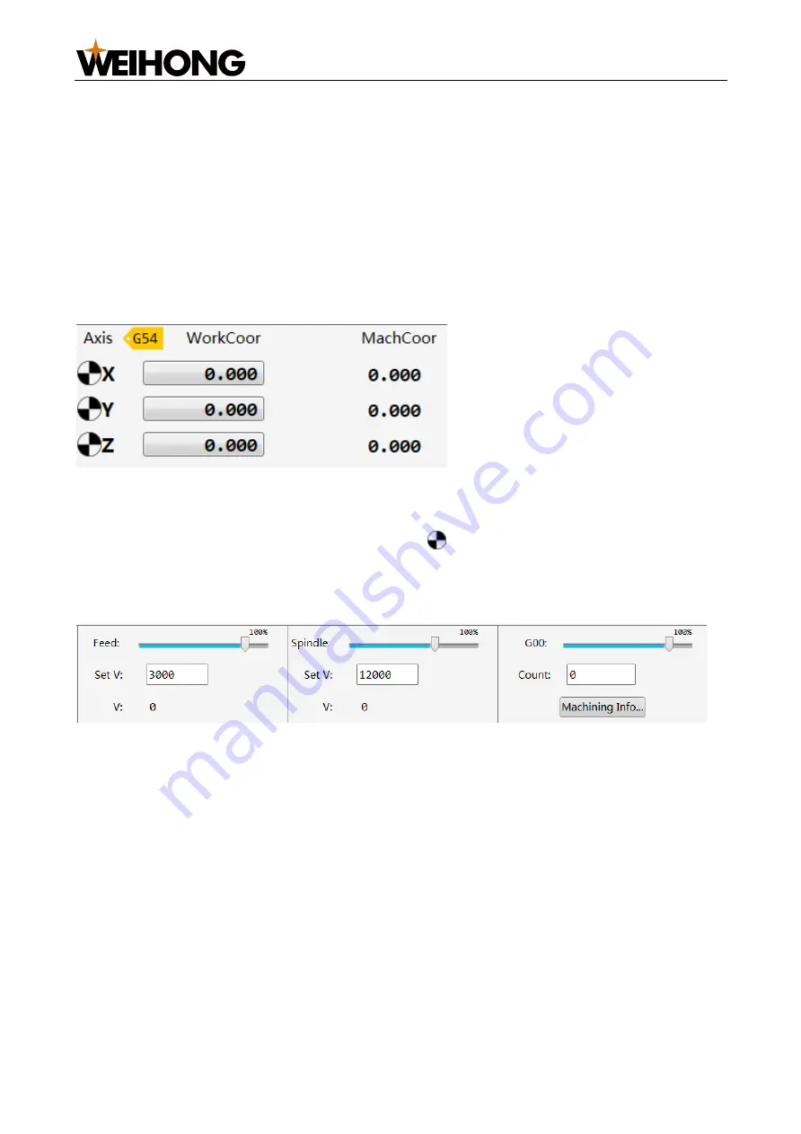
1.3.3.4 Override Setting Area 

The override setting area is shown below: 


  In this area, you can set the spindle rotational speed, feed rate and G00 speed 

parameters by entering values in the corresponding field. 

  You can adjust the spindle rotational speed, feed rate and G00 override/multiplier 

by dragging the corresponding slider. 
 

Actual spindle rotational speed = Spindle rotational speed multiplier * Spindle rotational speed setting 
 
Actual machining speed = Feed rate multiplier * Feed rate setting  
 
Actual G00 speed = G00 multiplier * G00 setting 


1.3.3.5 Machining Information Area 

The machining information area is shown below: 

Summary of Contents for Ncstudio Phoenix

Page 1: ...orts 13 2 3 Signal Type 13 2 3 1 Switch Value Input Signal 14 2 3 2 Relay Output Signal 14 2 3 3 Relay Output Signal 14 2 3 4 Command Pulse Signal 15 3 Machine Debugging 16 3 1 Overview 16 3 2 Install the Software 16 3 3 Modify I O Port Polarity 16 3 4 Set Debugging Parameters 17 3 5 Check Axis Direction 18 3 6 Go to Mechanical Origin or Set Datum 19 3 6 1 Making Axes Go to Mechanical Origin 19 3 ...

Page 2: ...ion Parameters 40 7 2 Adding Common Parameters 41 7 3 Changing Password 42 7 4 Switching System Language 43 7 5 Data Backup 43 7 6 Remote Assistance 43 7 7 Using NcGateway 43 7 8 M Codes 43 7 9 Software Registration 44 8 NcConfig 45 8 1 Opening NcConfig 45 8 2 Configuring Device 45 8 3 Configuring Machine Parts 46 8 3 1 Configure M Codes 46 8 3 2 Configure Function Buttons 47 8 3 3 Configure the T...

Page 3: ...Calibration 57 10 7 Going to Workpiece Origin 57 10 8 Going to Fixed Point 58 10 9 MDI 58 10 10 Clearing Drive Alarms 58 10 11 Reconnecting to the Controller 58 10 12 Switching between Multi Z Modes 59 Legal Notices 60 Requirements of Use 60 Intellectual Property Rights Notice 60 Termination 61 ...

Page 4: ... Lambda 21A Applicable to non bus control systems o Lambda 20A and so on EX series terminal board EX31A For the hardware connection diagram see section 1 2 Hardware Connection Diagram Software For introduction of the NcStudio Phoenix Three axis Engraving System software interface see section 1 3 Software Interface 1 2 Hardware Connection Diagram Hardware connection method varies based on the contr...

Page 5: ...ELECTRONIC TECHNOLOGY CO LTD 2 61 1 3 Software Interface This section gives you a brief introduction of the software interface of the NcStudio Phoenix Three axis Engraving System 1 3 1 NcConfig The homepage of NcConfig is shown below ...

Page 6: ...debugged in the function area 1 3 1 2 Project Configuration Area Click the Project or Configuration tab in the project configuration area s lower part to use different functions If the Project tab is not displayed in this area go to View Project in the menu bar Functions on the Configuration page Topology configuration Machine parts Port mapping Port protection 1 3 2 NcTune The homepage of NcTune ...

Page 7: ...上海维宏电子科技股份有限公司 SHANGHAI WEIHONG ELECTRONIC TECHNOLOGY CO LTD 4 61 1 Menu bar 2 Status bar 3 Welcome page 1 3 3 NcStudio The homepage of NcStudio is shown below ...

Page 8: ...ow Desktop and Exit Program Machining Wizard Machining Information and Machining Statistics Machine Single Block Execution HW Guide Current Point as Work Zero Cycle Start Cycle Pause Cycle Stop Simulate Resume Jiggle Homing To Work Zero To Fixed Point Centering MDI Datum Setting Adjustment Datum Cancel Double Y Jiggle Double Y Origin Detection Clear Servo Alarm Reconnect Drive and Reconnect Contro...

Page 9: ... system and the mechanical and workpiece coordinates of the axes After an axis has gone to the machine origin the icon will be displayed before the axis in this area 1 3 3 4 Override Setting Area The override setting area is shown below In this area you can set the spindle rotational speed feed rate and G00 speed parameters by entering values in the corresponding field You can adjust the spindle r...

Page 10: ... operation modes Auto o The loaded program is displayed in this mode o Common function Going to the fixed point o Common ports Spindle Cool Vacuum and Lube The common ports can be modified in NcConfig Manual o Axis buttons control of the axis movement in each direction Jog Click and hold an axis button to make the target axis move in the target direction continuously at the relatively lower speed ...

Page 11: ...ndle Cool Vacuum Lube etc The common ports can be modified in NcConfig Homing o Tick Execute homing when software starts to make the axes go to the mechanical origin upon software start o You can also check and clear the homing average values in this area 1 3 3 8 Operation Button Bar You can use the following functions with buttons in the operation button bar In Auto and Manual modes Loading and u...

Page 12: ... Network port For network connection 3 24V DC power supply port For connection to a 24V DC power supply 4 LED indicator Shows the current system status o ON The system is powered on o OFF The system is not powered on 5 Lambda controller port Phoenix bus RS485 port For connection to the Lambda controller 6 Operation panel port Phoenix bus RS485 port For connection to the operation panel 7 VGA displ...

Page 13: ... following content introduces port definitions for the Lambda 21B controller as an example Multiple EX31A extension terminal boards can be connected to the Lambda 21B controller to meet your needs The port definitions are shown below 2 1 3 EX31A Select extension terminal boards based on your needs EX31A Supports 10 channel input and 10 channel output ...

Page 14: ... ELECTRONIC TECHNOLOGY CO LTD 11 61 EX35A Supports 32 channel output EX36A Supports 32 channel input Port definitions of the Lambda 21B connected to two EX35A terminal boards and one EX36A terminal board are shown below as an example ...

Page 15: ...上海维宏电子科技股份有限公司 SHANGHAI WEIHONG ELECTRONIC TECHNOLOGY CO LTD 12 61 ...

Page 16: ...n below 5V Provides power supply for the operation panel Tx_N Sends differential signal NC Needs no wire connection Rx_P Receives differential signal GND Connects to the ground Tx_P Sends differential signal Rx_N Receives differential signal 2 3 Signal Type The following signal types are supported Switch Value Input Signal Relay Output Signal ...

Page 17: ...nected to the COM port inputs are active in high voltage When the common terminal board S of the Lambda controller is connected to the 24V port inputs are active in low voltage 2 3 2 Relay Output Signal The Lambda controller outputs relay signals The load capacity of relay output contact points is AC 7A 250V or DC 7A 30V If high power load is needed a contactor should be connected as follows The f...

Page 18: ... ELECTRONIC TECHNOLOGY CO LTD 15 61 The figure is as follows 2 3 4 Command Pulse Signal Pulse commands that control the controller s motion consist of pulse direction negative logic as shown below The maximum pulse frequency is 1MHz ...

Page 19: ...e machine can be powered on normally The USB flash drive storing the installation package is connected to the USB port of the NC65C host Follow the steps below to install the software 1 Double click the installation package The installation wizard window is displayed 2 Select the installation language Go to OK Next 3 After all settings are finished click Finish 3 3 Modify I O Port Polarity After t...

Page 20: ...ing functions are also supported o To test port signal output Click Test On Test Off When the port symbol becomes or the port is under test o To cancel testing of the selected port Click Cancel Test o To cancel testing of all ports Click Cancel All o To set sampling interval click Filter and drag the Interval slider The system will rule out signals whose duration is smaller than the interval 3 4 S...

Page 21: ...er computer If the Electronic gear ratio numerator Electronic gear ratio denominator value is larger than 1 the servo drive enlarges the pulse frequency If the Electronic gear ratio numerator Electronic gear ratio denominator value is smaller than 1 the servo drive shrinks the pulse frequency o Pitch The movement or rotation angle of the feed axis per lead screw turn 3 5 Check Axis Direction Deter...

Page 22: ...mechanical origin Applicable to incremental encoders Set datum Applicable to absolute encoders Before making the axes go to the mechanical origin or setting datum ensure that there is no drive or motor alarm 3 6 1 Making Axes Go to Mechanical Origin The mechanical coordinate system is the inherent coordinate system of the machine itself The origin of the mechanical coordinate system is called mech...

Page 23: ...bar go to Machine Homing to open the Home dialog box To make the Home dialog box automatically displayed when the software is started tick Dialog box pops up when cycle starts at the dialog box lower left corner o To make the X Y Z axis go to the mechanical origin click X axis X Y axis Y Z axis Z o To make all axes go to the mechanical origin click All Axes A o To set the current position as the m...

Page 24: ...ce is selected as the workpiece origin origin of the axis coordinate system of the machining paths The workpiece origin is fixed relative to the points on the workpiece and mobile relative to the mechanical origin Programmers select the workpiece origin commonly under considerations of convenience for programming and size conversion and less machining error You can select one from the following me...

Page 25: ...lick the WCS pull down menu Workpiece coordinate systems of G54 G59 are supported The default workpiece coordinate system is G54 3 Set Centering Type to Line 4 Optional If an edge finder is used for more accurate positioning follow the steps below a In the Spindle speed field enter the target spindle speed during centering Its value should not be too large and is set to 500 r min by default b Clic...

Page 26: ...arameters 1 Click the Offset tab in the function window 2 Select the target workpiece coordinate system such as G54 3 Enter X Y Z axis workpiece offset in the X Y Z fields 4 Click the Set buttons behind the X Y Z fields In the popped up dialog box click Yes to set the X Y Z axis workpiece coordinate of the current point to 0 5 Optional Enter X Y Z axis public offset values in the X Y Z fields in t...

Page 27: ...r o Z FixedPoint Z axis mechanical coordinate of the fixed tool sensor o LowestPoint Mechanical coordinate of the Z axis lowest point during tool calibration 5 Select one from the following tool calibration methods o Fixed calibration o First time calibration Calibration after tool change o Mobile calibration 3 7 4 1 Fixed Calibration If a tool is replaced due to being broke or other reasons the l...

Page 28: ...ations are used to record tool differences into the workpiece offset The operations are applicable to machine without automatic tool change functions and need to be executed every time a tool is changed Before executing first time calibration calibration after tool change operations Set the manufacturer parameter Tool Calibration Type to 2 Control the Z axis to move to the work piece surface and e...

Page 29: ...ate system will be changed Before executing mobile calibration ensure that Set the manufacturer parameter Tool Calibration Type to 1 In the Calibration Mode area of the Calibration tab Click Z Mobile Cali The system executes tool calibration at the current position and records the calibration result into the tool offset parameter 3 7 5 Setting Tool Compensation Parameters For details see section 3...

Page 30: ...machine movement or consume machine or workpiece resources Only the machining path and process are displayed in the software for you to spot possible problems and edit the program accordingly Follow the steps below to run simulation 1 In Auto or Manual mode select one from the following methods to access simulation mode o In the operation button bar click Simulate o In the menu bar go to Machine S...

Page 31: ...lect one from the following methods o Press the F10 key o In the operation button bar click o In the menu bar go to Machine Cycle Pause To stop machining select one from the following methods o Press the F11 key o In the operation button bar click o In the menu bar go to Machine Cycle Stop To resume machining from the interrupted position in case of power off emergency stop or other exception sele...

Page 32: ...le in the menu bar 5 1 2 Unloading a Program Select one from the following methods to unload a machining program In the operation button bar click Unload In the menu bar go to File Unload 5 1 3 Creating Editing Deleting and Renaming a Program Follow the steps below 1 In the function window click the Program Management tab 2 Select the target path in the upper left corner All g eng dxf nc plt txt n...

Page 33: ...e Block Execution in the menu bar to enable single block machining mode 2 Select one from the following methods to make the system run a command line and pauses o Press the F9 key o In the operation button bar click o In the menu bar go to Machine Cycle Start 3 Repeat step 2 to make the system run the next command line until all commands are executed 5 4 Selective Machining In this mode you can sp...

Page 34: ... default values The default start row is the first row and the default end row is the last row 4 Select one from the following methods to start selective machining o Press the F9 key o In the operation button bar click o In the menu bar go to Machine Cycle Start 5 5 ENG Tool and Line Selection If the loaded program is an ENG file you can specify a tool to run certain command lines Follow the steps...

Page 35: ...Y CO LTD 32 61 2 To specify the tool set Select No to ON A selection box column will be displayed before the tool number column Tick the target tool number To modify a tool number set Modify No to ON The Modify No column will be displayed as shown below ...

Page 36: ...sing area enter values in the Start Row and End Row fields Click OK 5 6 Advanced Machining Advanced machining includes adding of machining path array rotation and mirroring 5 6 1 Array Array machining means to copy the machining path along a rectangular array Follow the steps below to use array machining 1 In Auto or Manual mode go to Advanced AdvAuto in the menu bar to open the AdvAuto window ...

Page 37: ...ber of rows and columns row interval and column interval in the Rows Columns Row Space R and Column Space C fields 5 6 2 Rotation and Mirroring Rotation means to rotate the machining path by a certain angle while mirroring means to generate a symmetrical path along the X axis or Y axis Follow the steps below to use the rotation and mirroring function 1 In Auto or Manual mode go to Advanced AdvAuto...

Page 38: ...y Y b Tick Mirror c Optional To adjust the position of the paths enter the target deviation in the Eccentricity L field The machining mode is set to Convention by default which means not to enable rotation or mirroring 5 7 Machining Cycle You can set the machining to be repeated for a certain number of times and at certain interval and check the current times of machining Every complete running of...

Page 39: ...子科技股份有限公司 SHANGHAI WEIHONG ELECTRONIC TECHNOLOGY CO LTD 36 61 2 Enter the target cycle times and interval in the Cycles and Interval fields The current times of machining will be displayed after Cycle Index ...

Page 40: ...low the steps below to check the machining information statistics In the menu bar go to Program Machining Information Machining Statistics to check corresponding information In the Machining Information window the movement range machining range and tool travel length are displayed In the Machining Statistics window you can search for machining records by name or date and clear records before a cer...

Page 41: ...上海维宏电子科技股份有限公司 SHANGHAI WEIHONG ELECTRONIC TECHNOLOGY CO LTD 38 61 ...

Page 42: ...arameters operating parameters feed axis parameters program parameters origin parameters tool parameters compensation parameters and equipment parameters You can search for a parameter by clicking a parameter type in the left list or clicking Search in the lower left corner entering the parameter name in the field and clicking Next 7 1 2 Drive Parameters After the system is connected to the drive ...

Page 43: ...d click Save To restore parameter default values click Reset 7 1 3 Tool Compensation Parameters If a tool is worn or changed the diameter or length of the new tool may be different In this case you need to modify the tool compensation parameter values to achieve accurate machining Before setting tool compensation parameters Set the global parameter Enable Tool Length Compensation to Yes Set the gl...

Page 44: ...e target field enter the measured value and click OK 7 2 Adding Common Parameters You can set target parameters to become common parameters and displayed under the Common tab of the function window Follow the steps below to add a parameter into the common parameter list 1 Click the Common tab in the function window 2 Click Set in the lower right corner to open the Usually Param window ...

Page 45: ... 4 After locating the target parameter click it and click Add The target parameter will also be displayed under the right Common Parameter List 5 Repeat step 3 and step 4 until all target parameters are added 6 Optional To remove a parameter from the common parameter list or adjust its position in the list click the parameter and click Delete Up Down 7 3 Changing Password The password is used to v...

Page 46: ...ing system remotely controlled by technical support personnel to help troubleshoot Before using the remote assistance service ensure that your computer is connected to the Internet Follow the steps below to use the remote assistance service 1 In the menu bar go to System Remote Assistance 2 Give the computer identification code and the verification code to the technical support staff for remote co...

Page 47: ... register the software if the software use period has or is about to expire or if the writing type does not match Follow the steps below to register the software 1 In the menu bar go to System About Register 2 Click Apply for reg and acquire the registration code by following instructions in the application guide or contacting the supplier 3 Enter the registration code in the Registration Code fie...

Page 48: ...lick the Configuration tab Go to NcStudio Hardware Connection and Configuration Topology Configuration 2 Right click on Topology Configuration and click Edit Topology or double click Topology Configuration to open the Topology Configuration dialog box 3 Configure the devices based on your demands o To add a controller terminal board click Add and double click the target controller terminal board i...

Page 49: ...nfigure the parts as shown below o Configure M codes o Configure function buttons o Configure the tool magazine o Configure saws o Configure dual drive o Configure dual work stations o Configure press wheels o Configure clamps o Configure the handwheel 8 3 1 Configure M Codes You can configure the M codes for control of machine movement and port status After a machine part is ticked and the settin...

Page 50: ...ndle switch going to workpiece origin cooling vacuum pump lubrication etc Before configuring function buttons tick required machine parts on the Components page Follow the steps below to configure function buttons 1 In the left Configuration list double click PanelConfig to open the PanelConfig page on the right 2 To add a function button click the pull down menu at the target position and select ...

Page 51: ...agazine capacity the maximum number of tools o DiskMagazine Set the parameter Tool magazine capacity the maximum number of tools and Count tool overtime maximum time waiting for tool count signals o ServoToolMagazine Set the parameter Tool magazine capacity the maximum number of tools and rotary axis name o Cylinder Select the cylinder type and set the parameter Cylinder count Multi Cylinder Singl...

Page 52: ...rk stations are enabled the system directly starts machining on work station 2 after machining on work station 1 is finished to save loading and unloading time and improve efficiency Follow the steps below to configure dual work stations 1 In the left Configuration list double click DoubleArea to open the DoubleArea page on the right 2 Double click the target PhysicalAddress field to specify a phy...

Page 53: ...lAddress field to specify a physical address controller and port for the corresponding logical address 8 3 9 Configure the Handwheel You can use a handwheel to control machine movement Follow the steps below to configure the handwheel 1 In the left Configuration list double click Handwheel Configuration to open the Handwheel Configuration page on the right 2 Set Turn on to ON 8 4 Set Port Mapping ...

Page 54: ... the software is closed the protected ports will be automatically closed or opened based on their port protection type There are several types of port protection Open The port will be automatically opened when the software is closed Close The port will be automatically closed when the software is closed Follow The protected port status will be turned the same with that of the port specified in the...

Page 55: ...have not been saved The symbol disappears after changes on the page are saved 8 6 Creating Multi configuration Installation Package You can create a complete installation package in the current system to keep a backup of the system files and a steady version of system Note A multi configuration installation package includes all folders whose names are started with DefaultConfig Follow the steps be...

Page 56: ...Functions supported by NcTune are displayed on the welcome page as shown below such as setting lead screw error compensation and centering parameters etc Select one from the following methods to open NcTune Open NcStudio In the menu bar go to System NcTune Close NcStudio In the NcStudio installation path C Program Files Weihong NcStudio Bin double click NcTune exe ...

Page 57: ...Package to open the Packup Tool dialog box 2 Enter a name for the installation package 3 Click Browse to select a storage path 4 Optional Click Advanced and set the following parameters Language The software supports interface in Chinese and English Parameter Migrate o Keep local manufacturer parameters Keeps manufacturer parameter settings o Keep local user parameters Keeps user local settings Au...

Page 58: ...00 represent steps of 0 001 mm 0 01 mm and 0 1 mm respectively 3 Rotate the axis knob to select the target axis 4 Rotate the handwheel control knob clockwise to run the machining program The program running speed is determined by how fast you rotate the handwheel control dial 10 3 Dual Y Origin Detection This function can be used when your machine has two Y axes that use incremental encoders Befor...

Page 59: ...chine Jiggle 2 In the right JiggleDistance area select or enter a movement unit step 3 Click axis buttons in the middle to control the target axis to move in the target direction The accumulated movement of the axes are displayed in the left JiggleCount area 10 5 Dual Y Axis Jiggle You can use this function to adjust the position of a single Y axis or both Y axes In the menu bar go to Machine Doub...

Page 60: ...ter jiggling are displayed in the Feedback area Note After jiggling the Y axes you need to set datum or make them go to the mechanical origin 10 6 Calibration If the motor feedback coordinates are different from the mechanical coordinates you can manually calibrate the axes to synchronize the actual position of the absolute encoder and update the mechanical coordinates by reading the encoder feedb...

Page 61: ...t or machining Follow the steps below to use the MDI function 1 In Auto or Manual mode go to Machine MDI in the menu bar 2 Enter a command in a field and click Execute to make the system run the entered command 10 10 Clearing Drive Alarms Some types of drive alarms can be cleared in the software In some cases after such alarms are cleared no other drive alarms will be reported and the system will ...

Page 62: ...connect Controller 10 12 Switching between Multi Z Modes This function is available in software with multiple Z axis configuration to switch between sequential movement mode and linkage movement mode Follow the step below to switch between the modes In the menu bar go to System Multi Z Mode Switching ...

Page 63: ...et server only if it is stipulated in explicit terms that you are allowed to use the Software Product on a network server or intranet server or you have purchased license for each node and terminal using the Software Product 6 You may NOT sublicense assign or transfer the license agreement 7 You may NOT or direct any third party to reverse engineer decompile or disassemble the Software Product 8 Y...

Page 64: ...ditions made in this agreement Once the license is terminated you are obliged to destroy all the copies of the Software Product or return them to Weihong Company Now we affirm that you have already read through this agreement and understood it thoroughly and agreed to comply with all of the terms and conditions of this agreement strictly Weihong Electronic Technology Co Ltd ...

Page 65: ...Shanghai Weihong Electronic Technology Co Ltd Address No 1590 Huhang Rd Fengxian Shanghai China 201401 Hot line 400 882 9188 Website www weihong com cn en SPECIALIZED CONCENTRATED FOCUSED ...

Reviews: