background image

Abisolier- und Crimpautomat /Stripping and crimping machine  

CA 100 / 4-10 


B-W20411-014.doc / Sep-15


19


8.3 

Wöchentliche Wartung 


8.3 

Weekly maintenance 

Zuführtopf ausblasen 

  Zuführtopf durch abschrauben des Griffes nach 

oben entnehmen. 

  Zuführgut aus dem Zuführtopf entleeren. 

  Den Topf mit Druckluft vorsichtig ausblasen. 

  Topf  wieder  aufsetzen  und  Befestigungsgriff 

anziehen. 


Blow out feeding bowl 

  Remove  the  feeding  bowl  to  the  upper  side  by 

unscrewing the handle. 

  Empty commodity out of the feeding bowl. 

  Blow feeding bowl out carefully. 

  Set  bowl  back  on  the  machine  and  tighten  the 

handle. 


Zuführrohr und Vereinzelungsblock reinigen 

  Die  Schraube  in  der  Mitte  des  Schwingförder-

oberteils  lösen  und  das  Schwingförderoberteil 
abheben. 

  Die  Werkzeugeinheit  auf  dem  Werkzeug-

schlitten 

nach 

hinten 

drücken 

und 

ab-

schwenken. 

  Mit 

dem 

Handschieber 

das 

Zuführrohr 

entleeren. 

  Schraube am Vereinzelungsblock lösen. 

  Zuführrohr nach oben herausziehen. 

  Vereinzelungsblock nach vorne abziehen. 

  Mit Hilfe von weicher, geeigneter Bürste  


(z.B. Pfeifenreiniger) und Spiritus reinigen. 

  Einbau in umgekehrter Reihenfolge. 


Clean feeding tube and singling unit 

  Release  the  screw  in  the  middle  of  the  feeding 

bowl, and lift off the feeding bowl. 

  Push  the  tool  unit  on  the  tool  slide  to  the  back 

and turn it downwards. 

  Empty the feeding tube by the manual slide. 

  Open the screw at the singling unit. 

  Pull out the feeding tube upwards. 

  Take off the singling unit to the front. 

  Clean by using a soft, applicable brush  


(e.g. pipecleaner) and ethyl alcohol. 

  Fitting in reverse order. 


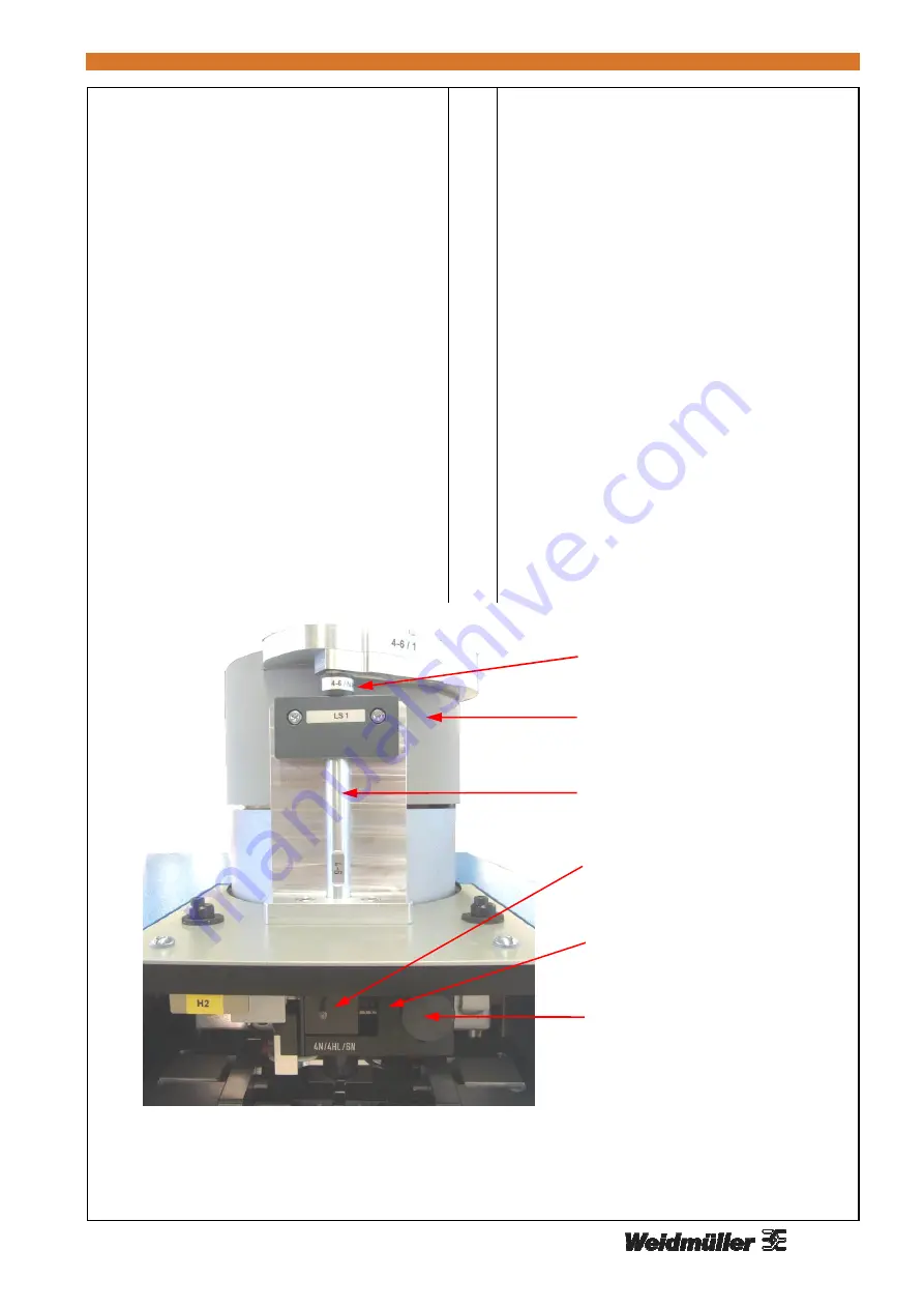
Bild / Picture 11: Zuführtopf, Zuführrohr und Vereinzelungsblock / 


feeding bowl, feeding tube and singling unit 


Zuführtopf/  
feeding bowl 

Zuführrohr/  
feeding tube 

Vereinzelungsblock/  
singling unit 

Schraube/  
screw 

Handschieber/  
manual slide 

Zuführrohr-Aufsatz/  
feeding tube – top part 

Summary of Contents for CA 100

Page 1: ...Bedienungsanleitung Operating Manual Abisolier und Crimpautomat CA 100 4 10 Stripping and crimping machine CA 100 4 10 Fabrikationsnummer Fabrication number Sample ...

Page 2: ...e CA 100 4 10 B W20411 014 doc Sep 15 2 Kontaktadresse Weidmüller Interface GmbH Co KG Postfach 3030 32720 Detmold Klingenbergstraße 16 32758 Detmold Telefon 49 0 5231 14 0 Telefax 49 0 5231 14 292083 E Mail info weidmueller com Internet www weidmueller com ...

Page 3: ... Erhöhter Ausschuss 25 9 3 Fehlermeldungen 26 10 Pneumatik Anschlussplan 28 11 Elektro Anschlussplan 29 12 Konformitätserklärung 30 13 Datensicherung 31 Table of contents 1 Safety instructions 4 1 1 General 4 1 2 Intended Use 4 1 3 Training of personnel 5 1 4 Special obligations of the person in charge 5 1 5 Using risks 5 2 Transport 5 3 Technical specifications 5 4 List of the tools 6 5 General v...

Page 4: ...Intended Use Stripping of insulated wires according to DIN EN 60228 VDE 0295 2005 Cross section 6 mm Feeding length 28 mm crimping length Crimping of loose Weidmüller ferrules with insulating collar See list of the tools Crimp form standard Nicht gestattet sind Verwendung der Maschine ohne Einweisung Verwendung außerhalb der Einsatzgrenzen Unwirksammachen von Sicherheitseinrichtungen Entfernen von...

Page 5: ...auchsgefahren Vor dem Wechsel von Ersatzteilen den Netz stecker ziehen und die Maschine vom Pneumatiknetz trennen Nach Abnehmen der Abdeckhaube darauf achten dass der Erdungsdraht gesteckt ist bevor die Maschine wieder geschlossen wird 1 5 Using risks Before changing spare parts remove the plug and disconnect the machine from the pneumatic supply system Should the removal of the cover be necessary...

Page 6: ... tongs cone 4 6 1 Zuführrohr Feeding tube 4 6 Zuführrohr Aufsatz Feeding tube top part 4 6 N HL Vereinzelungsblock Singling unit 156 3 Drahtfixierung Wire holder 4 6 Auslösevorrichtung Starting unit E H Abisoliermesser Stripping blades V Messer V Blades Messerunterlage hinten beidseitig Blade spacer behind on both sides 0 5 mm Einstellung Exzenter Richtwert Adjustment eccentric guiding value 6 Hül...

Page 7: ... path Lichtschranke Light barrier Schwingförderoberteil Feeding bowl Zuführrohr Feeding tube Wartungseinheit Maintenance unit Drehriegel Knob Einführtrichter Feeding funnel Frontplatte Front panel Abisolierrest Behälter Stripping waste container Netzfilter Modul Filter module Einstellknopf Drahthaltezange Adjusting knob of the wire holding tongs Touchdisplay Bild Picture 1 Gesamtansicht General vi...

Page 8: ...n und anschließend wieder verriegeln Hülsen in das Schwingförderoberteil einfüllen Den Netzschalter auf dem Netzfilter Modul einschalten Die Maschine fährt in die Grundstellung Wenn das Zuführrohr nicht gefüllt ist startet der Schwingförderer automatisch Menü 1 erscheint im Display Nach Ablauf der eingestellten Anzahl bei Service blinkt SERVICE beim einschalten der Maschine auf Die Meldung kann mi...

Page 9: ... 1 voll Statusanzeige SF 0 aus 1 ein 3 Einstellmenue 3 1 Nur abisolieren 0 abisolieren und crimpen 1 nur abisolieren Nach dem Einschalten der Maschine ist Option Abisolieren 0 eingestellt 6 3 Menus up or down E select 1 production menu Status Ready Strip Crimp Power vibrating conveyor VC d pcs C 5 s delete Error Message first number Step 1 15 step second number FT stripping crimping third number V...

Page 10: ...f E wird der Status 0 Ausgang ist inaktiv 7 Allgemeine Daten 8 Schrittzeiten 9 PC Daten 10 Sprache deutsch englisch französisch italienisch niederländisch 4 plant data menu tcounter total piece number cycle operating time of one cycle 5 test inputs No status I or 0 Name of the assembly part 6 test outputs No status I or 0 Name of the assembly part For simulation By pushing on E the status will be ...

Page 11: ...hrtrichter den Arbeitszyklus aus Er muss gerade abgeschnitten sein und darf keine Knicke und Bögen aufweisen 6 5 Wire feeding The wire triggers the working cycle by inserting into the feeding funnel It has to be cut off straight and may not have any bends or bows richtig correct falsch incorrect 40 mm correct incorrect schräger Schnitt oblique cut abgescherter Leiter deformed wire herausgezogener ...

Page 12: ...ken und abschwenken Mit dem Handschieber das Zuführrohr entleeren Schraube am Vereinzelungsblock lösen Zuführrohr nach oben herausziehen Vereinzelungsblock nach vorne abziehen Einbau in umgekehrter Reihenfolge 7 1 Ferrule feeding Feeding bowl Feeding tube Singling unit Release the screw in the middle of the feeding bowl and lift off the feeding bowl Push the tool unit on the tool slide to the back...

Page 13: ...Drahtfixierung und Auslösevorrichtung Wire holder and Starting unit 7 3 Auslösevorrichtung Werkzeugeinheit in Grundstellung Befestigungsschraube lösen und Drahtfixierung abziehen Das linke Abisoliermesser ausbauen Auslösevorrichtung abschrauben und aus tauschen 7 3 Starting unit Tool unit in starting position Release the fixing screws and remove the wire holder Remove the left stripping blade Unsc...

Page 14: ...einbauen Exzenter einstellen und Schrauben festdrehen Exzenter nicht vertauschen 7 5 Stripping blades Caution Blades are sharp Tool unit in starting position Release the screws of the eccentrics Remove the eccentrics Remove the blades turn them or replace them by new ones Mount the blades and the spacers Adjust the eccentrics and tighten the screws Do not mix up the eccentrics V Messer V blade Mes...

Page 15: ...en Knöpfe nach unten drücken die Hülsenhalteinheit nach vorne kippen und herausnehmen 7 6 Ferrule holders Push the tool unit on the tool slide to the back turn it downwards and pull it to the front again Remove the ferrule out of the ferrule holders Push down the red knobs turn the ferrule holding unit to the front and take it out Führungsstift Guiding pin Kontakthaltebacken Contact holders Roter ...

Page 16: ...euge ersetzen Die Hülsenhalteeinheit zuschwenken und die Werkzeugeinheit in Grundstellung bringen 7 7 Crimping tool The crimping tool consists of the die the anvil and the stopper Push the tool unit on the tool slide to the back turn it downwards and pull it to the front again Remove the ferrule out of the ferrule holders Push down the red knobs and turn the ferrule holding unit to the front Relea...

Page 17: ...llieren ob der Schwenkzylinder eingerastet ist 7 8 Tool unit Tool unit in starting position Release the locking screws by approximately 5 rotations Push the tool unit on the tool slide to the back turn it downwards and pull it to the front again Release the fixing screws and remove the tool unit Check the position of the 4 O rings in the fixing parts Push the two crimping tools and stripping blade...

Page 18: ... the interior of the machine with compressed air Do not use spray oil or spray grease If possible use silicone or PTFE oil Teflon oil Use grease which is applicable for bearings and sliding surfaces The display and touch screen are made of plastic and they do not may come into contact with hard objects The surface of the touch screen can be cleaned with a soft cloth without the use of solvents 8 2...

Page 19: ... schwenken Mit dem Handschieber das Zuführrohr entleeren Schraube am Vereinzelungsblock lösen Zuführrohr nach oben herausziehen Vereinzelungsblock nach vorne abziehen Mit Hilfe von weicher geeigneter Bürste z B Pfeifenreiniger und Spiritus reinigen Einbau in umgekehrter Reihenfolge Clean feeding tube and singling unit Release the screw in the middle of the feeding bowl and lift off the feeding bow...

Page 20: ...Hülsenhaltebacken entfernen Die roten Knöpfe nach unten drücken und die Hülsenhalteinheit nach vorne kippen Hülsenhaltebacken mit Hilfe von Pinsel und Spiritus reinigen Die Führungsstifte und Führungssschrauben leicht einölen Clean ferrule holders Push the tool unit on the tool slide to the back turn it downwards and pull it to the front again Remove the ferrule out of the ferrule holders Push dow...

Page 21: ...ten Werkzeugeinheit in Grundstellung hoch schwenken Schwenkzylinder einrasten Klemmschraube so festdrehen dass die Werkzeugeinheit durch ihr Eigengewicht noch nach unten schwenkt Durch Schwenken von Hand kontrollieren ob der Schwenkzylinder korrekt eingerastet ist Clean crimping zone see pictures on following page Tool unit in starting position Release the locking screw by approximately 5 rotation...

Page 22: ...hine CA 100 4 10 B W20411 014 doc Sep 15 22 Werkzeugeinheit Rückansicht tool unit back view Bild Picture 14 Werkzeugeingheit tool unit Befestigungsschrauben fixing screws Klemmschraube locking screw Crimpbacke crimping flang Abisolierbacke stripping flang ...

Page 23: ... einfetten Gehäuse wieder aufsetzten und festschrauben Darauf achten dass der Erdungsdraht gesteckt ist bevor die Maschine wieder geschlossen wird Drive link Remove screws of the case Take the cover off in upper side Lubricate the drive link at the pivot point on the upper and lower side with grease Fit the case and thighten Take care that the earth wire is connected be fore re closing the machine...

Page 24: ...raubt werden Den Filter in Lösungsmittel z B Benzin oder Petroleum legen gut durchschwenken und trocknen Achtung Behälter nur mit Wasser reinigen Pneumatic maintenance unit Let off the condensed water in time Therefore remove drain screw The tank can be cleaned with water To remove the tank disconnect the air supply The filter element can be unscrewed for cleaning Put it into purifying agent benzi...

Page 25: ...ltebacken sind beschädigt Hülsenhaltebacken austauschen Eine zweite Hülse befindet sich zwischen den Hülsenhaltebacken Hülse entfernen Der Draht wird eingezogen Den Druck der Drahthaltezangen erhöhen Riefen an der Isolierung Den Druck der Drahthaltezangen verringern 9 2 Increasing refuse The stripping blades are damaged or incorrectly mounted Correct or change the blades The stripping waste contai...

Page 26: ...n Fehler Frontp K1 Schalter S 6 defekt Fehler beim Schließen der Frontplatte Enter Taste 4 s drücken Fehler Frontplatte K2 Schalter S 6 defekt Fehler beim Schließen der Frontplatte Enter Taste 4 s drücken Frontplatte auf Frontplatte schließen Zufuehrung gest Zufuehrung SF gestört Schwingfördertopf überprüfen no op voltage 15 operating voltage 15V failed no op voltage 24V operating voltage 24V fail...

Page 27: ...Eine Hülse blockiert die Zuführung Fehler Datenver falsche Datenversion bei USB Datenübertragung mit PC Fehler USB Kabel USB Kabel nicht gesteckt Draht entnehmen Draht entnehmen S8 Drahtueberw Draht entnehmen S8 überprüfen S1 start 0 S1 faulty S1 start 1 S1 faulty S2 Crimp clos 0 Check S2 and Y2 S2 Crimp clos 1 Check S2 and Y2 S3 stripposit 0 Check S3 and Y3 S3 stripposit 1 Check S3 and Y3 S4 Tool...

Page 28: ...Abisolier und Crimpautomat Stripping and crimping machine CA 100 4 10 B W20411 014 doc Sep 15 28 10 Pneumatik Anschlussplan 10 Pneumatic diagram ...

Page 29: ...Abisolier und Crimpautomat Stripping and crimping machine CA 100 4 10 B W20411 014 doc Sep 15 29 11 Elektro Anschlussplan 11 Electric diagram ...

Page 30: ...g von Maschinen DIN EN 60 204 1 2010 Störaussendung EN 61000 6 4 2011 Störfestigkeit EN 61000 6 2 2011 EMV Flicker EN 61000 3 3 2009 EMV Oberschwingung EN 61000 3 2 2011 Detmold den Dr Christoph Fröhlich Geschäftsführer The company Weidmüller Interface GmbH Co Klingenbergstraße 16 D 32758 Detmold attests in sole responsibility that the product Stripping and crimping machine CA 100 4 10 Fabrication...

Page 31: ...250 sec 6 Schlitten zur 0 000 sec 7 Messer auf 0 150 sec 8 Schwenken Cri 0 100 sec 9 Schlitten vor 0 000 sec 10 Crimpen zu 0 050 sec 11 Crimpen zu IO 0 250 sec 12 H Halter auf 0 050 sec 13 Crimpen auf 0 150 sec 14 Drahthalt auf 0 100 sec 15 Crimpen auf 0 050 sec 16 Schlitten zur 0 050 sec 17 Schwenken Ab 0 120 sec 18 Schlitten vor 0 000 sec 19 Startfreigabe 0 020 sec 20 Zeit 1 000 sec 21 Zeit 1 00...

Reviews: