CFW501 | 39
Technical Specifications
E
ng
lis
h
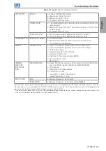
OUTPUTS
(*)
RELAY
2 relays with NA/NF contact.
Maximum voltage: 240 Vac.
Maximum current: 0.5 A.
Programmable functions.
TRANSISTOR
1 insulated digital output open sink (uses as reference the 24-Vdc
power supply).
Maximum current 150 mA
(**)
(maximum capacity of the 24-Vdc)
power supply.
Programmable functions.
POWER SUPPLY
24-Vdc power supply. Maximum capacity: 150 mA
(**)
.
10-Vdc power supply. Maximum capacity: 2 mA.
COMMUNICATION INTERFACE RS485
Insulated RS485.
Modbus-RTU, BACnet or N2 protocol with maximum
communication of 38.4kbps.
SAFETY
PROTECTION
Overcurrent/phase-phase short circuit in the output.
Overcurrent/phase-ground short circuit in the output.
Under/overvoltage.
Overtemperature in the heatsink.
Overload in the motor.
Overload in the power module (IGBTs).
External alarm / fault.
Setting error.
HUMAN-
MACHINE
INTERFACE
(HMI)
STANDARD HMI
9 keys: Start/Stop, Up arrow, Down arrow, Direction of Rotation,
Jog, Local/Remote, BACK/ESC and ENTER/MENU.
LCD display.
View/edition of all parameters.
Indication accuracy:
- current: 5 % of the rated current.
- speed resolution: 1 rpm.
ENCLOSURE
IP20
Models of frame A, B, C and D.
NEMA1/IP20
Models of frame A, B, C and D with kit NEMA1.
(*)
The number and/or type of analog/digital inputs/outputs may vary. Depending on the Plug-in module (accessory) used. For
the table above, it was considered the CFW500-CRS485 plug-in module. For further information, refer to the programming
manual and the guide supplied with the optional item or in the CD-ROM.
(**)
The maximum capacity of 150 mA must be considered adding the load of the 24-V power supply and transistor output, that
is, the sum of the consumption of both must not exceed 150 mA.
Table 8.1 (cont.):
Electronics/general data

