


10 | CFW501
Installation and Connection
E
ng
lis
h
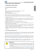
3.1.2.1 Cabinet Mounting
For inverters installed inside cabinets or metallic boxes, provide proper exhaustion, so
that the temperature remains within the allowed range. Refer to the dissipated powers
in
As a reference,
shows the air flow of nominal ventilation for each frame.
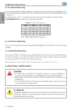
Cooling Method:
internal fan with air flow upwards.
Table 3.1:
Air flow of the internal fan
Frame
CFM
I/s
m
3
/min
A
20
9.4
0.56
B
30
14.1
0.85
C
30
14.1
0.85
D (T2)
*
100
47.2
2.83
D (T4)
**
80
37.8
2.27
(*)
T2 - CFW501 Frame D line 200 V (200...240 V).
(**)
T4 - CFW501 Frame D line 400 V (380...480 V).
3.1.2.2 Surface Mounting
illustrates the procedure for the installation of the CFW501 on the mounting
surface.
3.1.2.3 DIN-Rail Mounting
The inverter CFW501 can also be mounted directly on 35-mm rail as per DIN EN 50.022.
For this mounting, you must first position the lock
(*)
down and then place the inverter
on the rail, position the lock
(*)
up, fixing the inverter.
(*)
The fastening lock of the inverter on the rail is indicated with a screwdriver in
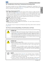
3.2 ELECTRICAL INSTALLATION
DANGER!
The following information is merely a guide for proper installation.
Comply with applicable local regulations for electrical installations.
Make sure the power supply is disconnected before starting the
installation.
The CFW501 must not be used as an emergency stop device. Provide
other devices for that purpose.
ATTENTION!
Integral solid state short circuit protection does not provide branch circuit
protection. Branch circuit protection must be provided in accordance
with applicable local codes.


