`çãéäÉíÉ=háí==^`qolp=
`çãéäÉíáçå=çÑ=~ëëÉãÄäó=Öêçìéë
1002
1001
1004
1003
21
21
564
564
564
13
2
2
2
1038
995
1000
1001
564
564
624
624
1005
1006
1007
1008
1009
1010
1011
1015
498
56
2
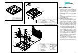
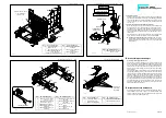
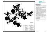
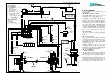
4.4 Fixing the air filter
Using two panel screws 21, start by mounting the side part 1004 onto
the outside part 1002. With countersunk screws 564 add afterwards
the inside part 1003 to the outside part 1002. Finally fix this unit with
screws 2 onto the rear panel, and with screws 2 and washers 13
onto the roof.
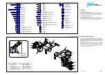
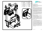
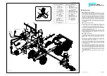
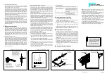
4.5 Connecting diagram for the clamp-type terminals
When removing the roof, you may also disconnect the cabling at the
pin and socket connector. For this purpose use the 7-pole pin termi-
nal 1000 and the 7-pole socket terminal 1001. Accordingly to the il-
lustration, a resistor 1038 for the roof lamps has to be mounted onto
the pin terminal and the antenna cable has to be soldered to the an-
tenna socket.
The illustration shows the different connections. To make both sides
clearly visible, you find two illustrations of the pin terminal 1000.
Installing the Diesel Engine Sound, Art.-No. 193: The Diesel
engine sound includes the loudspeaker, which can be stuck into
the area provided on the underside of the roof, using double sided
adhesive pads.
R
mêÉJ~ëëÉãÄäó=çÑ=íÜÉ=ÄìãéÉê
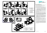
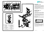
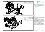
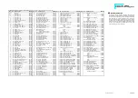
Assembly of headlights and blinkers
Cut the piece of reflector foil 1037 (no ill.) to size according to the
size of the headlight housings 1006 and 1007 and lay these pieces
into the lamp cases. Accordingly to the drawing, afterwards press
one bulb into each of the clips provided on the lamp housings. As per
drawing feed the wires through the narrow slots inside these lamp
cases outwards.
First fit the lens 1010 of the left blinker into the corresponding opening
on the bumper 1005 by pressing it into place from the inside, flush to
the left, and add a headlight lens 624 with the funnel-shaped ribbing
showing outwards. The lugs on the top and bottom of the outer left
blinker lens 1008 fit into the slots in the grooves on the left bumper
side. Now set the left-hand lamp housing 1006 that way onto the fix-
ing domes inside the bumper that the upper collar of the blinker lens
gets fixed behind the cut-out of the headlight housing. Finally fix the
housing with screws 564. Do the assembly of the right-hand head-
light housing 1007 in the same way.
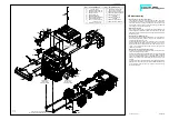
S
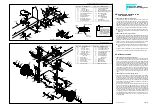
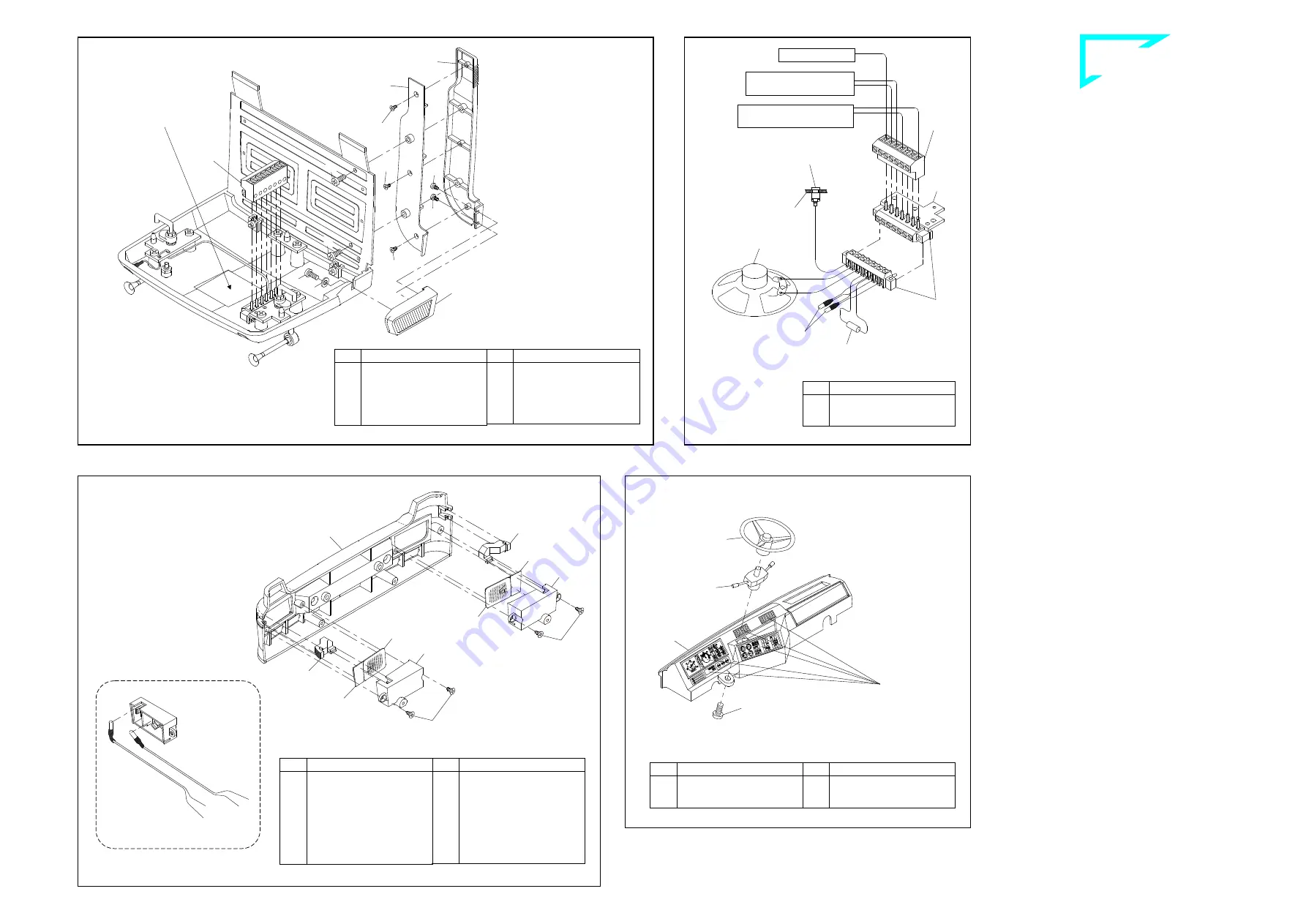
mêÉé~ê~íáçå=çÑ=íÜÉ=Ç~ëÜÄç~êÇ
Peel the stickers showing the instruments and switches from the de-
cal sheet 1014 and stick them in place on the dashboard 1015. With
screw 2 fix then the shift for the switch 498 onto the dashboard and
press the steering wheel 56 onto this shift.
Fixing the air filter ill. 4.4
80-e.DOC / K-Actros
Page 5
Connecting diagram for the clamp-type terminals ill. 4.5
Pre-assembly of the bumper ill. 5
Preparation of the dashboard ill. 6
Qty.
No. Assembly part
1
1038 Resistor for roof lamps,
80.6
Ω
/ 0.5 W
Space for the attachment
of the loudspeaker
of Art.-No. 193
Cab roof
Loudspeaker of
Art.-No. 193
Roof lamps
Connection of roof lamps
from switch panel
Antenna receiver
Loudspeaker connection
to the engine sound
Antenna socket
B-233-5
Stickers taken
off the decal
sheet 1014
Inserting the bulbs
B-80-3
B-233-4b
B-233-5
Qty.
No. Assembly part
1
2 Screw M3 x 8
1
56 Steering wheel
1
498 Switch dashboard
Qty.
No. Assembly part
1
1014 Decal sheet ACTROS
1
1015 Dashboard ACTROS
Qty.
No. Assembly part
1
1008 Blinker lens outside -lh-
ACTROS
1
1009 Blinker lens outside -rh-
ACTROS
1
1010 Blinker lens -lh- AC-
TROS
1
1011 Blinker lens -rh- AC-
TROS
1
1037 Reflector foil
Qty.
No. Assembly part
4
564 Countersunk tapping
screw 2.2 x 4.5
2
624 Headlight lens, MAN
4
713 Bulb 3V, 100mA
1
1005 Bumper ACTROS
1
1006 Headlight housing -lh-
ACTROS
1
1007 Headlight housing -rh-
ACTROS
Qty.
No. Assembly part
1
1002 Air filter, outside part
ACTROS
1
1003 Air filter, inside part
ACTROS
1
1004 Air filter, side part
ACTROS
Qty.
No. Assembly part
3
2 Screw M3 x 8
1
13 Washer 3.2
2
21 Tapping screw 2.2 x 4.5
3
564 Countersunk tapping
screw 2.2 x 4.5
1
1001 7-pole socket terminal

