`çãéäÉíÉ=háí==^`qolp=
`çãéäÉíáçå=çÑ=~ëëÉãÄäó=Öêçìéë
64
62
13
13
949
949
1056
1056
54
54
2
60
61
63
59
708
359
2
13
2
58
391
1582
109
1044
653
654
6
1039
1041
1045
653
654
115
1042
2
1043
1039
NP
aêáîÉ=ëÉÅíáçå=
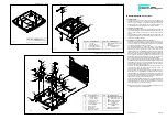
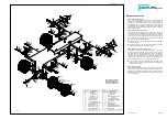
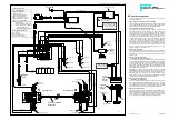
13.1 Mounting the motor and gearbox
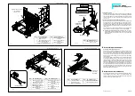
Use screws 2 to bolt the gear cover 59 to the motor 708 (we supply
the white motor pinion 60 (14t.) already mounted to the motor shaft).
Before assembling the gearing lubricate the gears and shafts lightly
with Vaseline. Then clip the joint ball 64 in the gear wheel 62. Lay this
gear wheel, the double pinion 61 with shaft 63 and -not to forget!- the
shim 391 in the gear housing 58 and use screws 2 and M3 nuts to
secure the gear housing to the cover. Once assembled, this unit is
inserted from above into the opening in the frame and secured at the
sides with screws 2, washers 13 and M3 nuts. At the same time the
drive shaft 359 is inserted at the joint balls between the gearbox and
the differential.
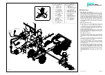
13.2 Mounting the speed controller
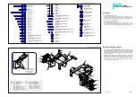
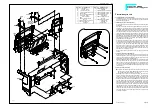
When affixing the speed controller 1582 please ensure that the
ribbon cable with the two lamp PCBs are located between the
frame and the screws used to affix the speed controller (ill. 8).
First mount each of the straight ends of the clamp fittings 54 along
with the tank supports 1056 to the right-hand side of the frame; for this
purpose use screws 949 and nuts M3.
Now set the speed controller into the tank supports. Lay the long ends
of the tank supports and the clamp fittings around the speed control-
ler and fix the clamp fittings from underneath to the screws using
washers 13 and nuts M3.
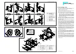
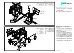
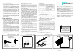
13.3 Mounting the exhaust unit
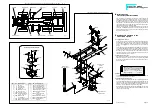
The threads in the plastic components are cut by the corresponding
screws; therefore before starting the assembly it is advisable first to
screw down them by approx. 2 mm and afterwards to unscrew them
again.
First press the outer exhaust panel 1040 into the slot on the lower
exhaust half shell 1042 and then mount the exhaust pipe 1043 with
one screw 57 and nut M3 (see small drawing).
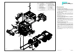
Using screws 115 and nuts 109 fix the inner exhaust panel 1039 onto
the frame. Now fit the lower half shell along with the premounted
outer panel into the inner exhaust panel and screw down screws 6
but do not fasten them.
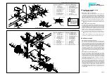
Lay the upper exhaust shield 1045 onto the upper exhaust half shell
1041, so that the narrow edge (approx. 2 mm) lays towards the frame;
connect both parts with screws 653 and nuts 654. For this purpose
use that plastic wrench 656 supplied with this kit. Afterwards slide
this premounted half shell into the inner exhaust panel; with it's slot
set it suitably onto the outer exhaust panel. Once all components fit
correctly, tighten screws
Finally add the front exhaust shield 1044 and fix it with four screws
653.
80-e.DOC / K-Actros
Page 10
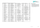
Drive section ill. 13
Qty.
No. Assembly part
11
--- Nut M3
9
2 Screw M3 x 8
2
6 Screw M3 x 25
4
13 Washer 3.2
2
54 Clamp fitting,
standard frame
1
57 Screw M3 x 10
1
58 Case for gear 116
1
59 Cap for gear 116
(1)
60 Motor pinion white,
14teeth
1
61 Double pinion
1
62 Gear wheel with
joint socket
1
63 Shaft for gear 116
1
64 Ball joint
2
109 Nut M2
2
115 Screw M2 x 8
1
359 Drive shaft 145mm
8
653 Hex head screw
M1.6 x 4
Qty.
No. Assembly part
1
391 Shim 5 x 10 x 1
4
654 Nut M1.6
1
656 Socket wrench 3.2 / 2.5
1
708 Bühler motor including
14 teeth pinion
2
949 Screw M3 x 35
1
1039 Exhaust panel, inside
1
1040 Exhaust panel, outside
1
1041 Exhaust half shell, top
1
1042 Exhaust half shell,
bottom
1
1043 Exhaust pipe
1
1044 Exhaust shield, front
1
1045 Exhaust shield, top
2
1056 Tank support for
square tank
1
1582 Speed controller,
square tank
B-80-7a
B-80-7b
Brake light
green/yellow
to the radio receiver
to battery
B-460-2

