`çãéäÉíÉ=háí==^`qolp=
`çãéäÉíáçå=çÑ=~ëëÉãÄäó=Öêçìéë
NT
qÜÉ=ÉäÉÅíêáÅ~ä=ëóëíÉã=
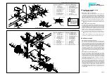
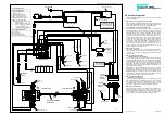
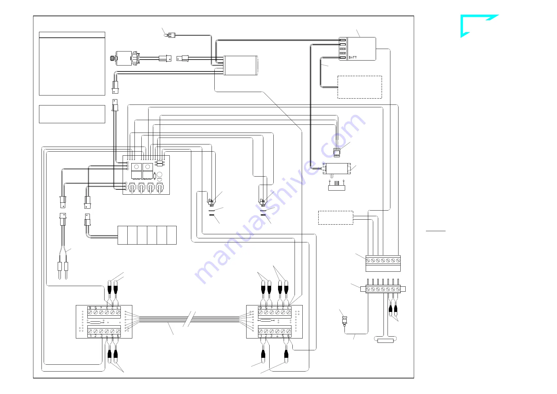
The wiring diagram shows the cable connections for the individual
electrical components.
17.1 Mounting the switching panel and lamp PCBs
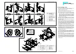
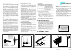
The switch panel is inserted into the seat rear panel of the cab. First
connect the bulbs and cables and then clip the lamp PCBs in place
at the front and rear in the supports provided for this purpose.
17.2 Information on the bulbs, troubleshooting
All the bulbs are 3-volt bulbs connected in series. This means that
the conductors are not each connected to the supply voltage, as in
an automobile. Instead, the ends are joined one to another to form a
chain and the ends of the chain are attached to the power supply.
Consequently just a single defective bulb will interrupt the entire cir-
cuit and none of the lamps in the chain will light. The best way to lo-
cate the defective bulb is to use a cable to bypass each of the bulbs
in the series, one after the other. When you bypass the defective
bulb, the rest in the chain will light. The reason for using a series cir-
cuit, which may appear to be complicated, is the low power consump-
tion. 3-volt bulbs use far less power than 12-volt bulbs in relation to
their brightness. The power consumed by a chain of up to five 3-volt
bulbs is just 0.1 A in the series connection which we use; 12-volt
bulbs, by comparison, would draw 0.3 A.
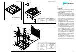
17.3 Wiring the roof lamps
Connect the red/black cable of the switch panel to the 7-pole socket
terminal provided for the roof. Then connect the bulb wires as well as
the resistor to the 7-pole pin terminal underneath the roof (see also il-
lustration 4.5).
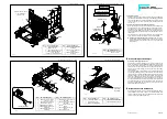
17.4 Wiring at the rear lamp PCB
(tail and brake lights, rear blinkers)
The red/black/yellow cable exiting the switch panel for the rear lamps
is routed under the frame and to the rear and connected to the PCB
- marked on the bottom with „H“ for rear - as shown in the illustration.
The green/yellow brake light cable coming from the speed controller
is also to be connected at this PCB. Once the bulb leads have been
attached, the PCB is clipped in place at the support which was previ-
ously affixed with adhesive pads.
Explanation: The green/yellow brake light cable connects the brake
light bulbs to ground when the vehicle is at a standstill. This circuitry
incorporates an element which limits the current to 750 mA and will
disable the circuit in case of an overload or short. Switching off the
supply voltage for about one second will reset this element, provided
that the reason for the malfunction has been corrected.
17.5 Wiring at the front lamp PCB
(headlamps, front blinkers)
The green/yellow/grey cable serving the lamps at the front also exits
from the switch panel and is routed below the frame and to the front
in exactly the same fashion. After connecting to the PCB - marked
on the bottom with „V“ for front - and connecting the bulb leads, the
lamp PCB is clipped in place in the support previously mounted.
17.6 Wiring the blinker switch
The green/brown/white cable for the blinker switch terminates in a
clamp-type connector (see therefore ill. 17a on page 14). This con-
nector is attached to the blinker switch (if the direction of travel does
not correspond to the blinking, please rotate it through 180°),
mounted beneath the steering servo, already illustrated in ill. 9.
80-e.DOC / K-Actros
Page 13
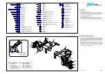
Wiring diagram of the electrical equipment ill. 17
Supplied with the kit:
No. Assembly part
568 Antenna socket
708 Drive motor
929 Clamp-type connector
1000 7-pole pin terminal
1001 7-pole socket terminal
1038 Resistor 80.6
Ω
/ 0.5W
1392 12V battery ACTROS,
1582 Speed controller, square tank
--- Blinker switch
--- Charging cable with AMP-plug
--- Set of circuit boards f. complete
chassis with lamp PCBs
--- Switch panel with jack bushes
Not supplied with the kit:
RC receiver
Steering servo
Servo connecting cable
Cable for receiver voltage
7-pole
socket
terminal
for roof
to the engine noise
(not incl. in the kit)
7-pole pin
terminal
for roof
Roof
lamps
80.6
Ω
Blinker switch
white
brown
green
black
red
Brake light
yellow/green
Motor
yellow
yellow
yellow
yellow
red
black
Antenna socket
brown/red/orange
Clamp
type
connector
re
d
b
la
c
k
re
d
b
la
c
k
y
e
llo
w
green
yellow
grey
Head lamps -lh-/-rh-
R
E
C
E
IV
E
R
(not incl. in the kit)
to the battery box of the
remote control system
or alternative to the
switch panel (ill. 20)
Speed controller
Antenna cable
b
la
c
k
re
d
Blinker -lh-
Blinker -rh-
12V Battery ACTROS
Switch panel
Charging
cable
black
red
blue
Jack bush
Jack bush
Knurled nut
Disc red
Knurled nut
Disc black
g
re
y
g
re
e
n
y
e
llo
w
Front lamp PCB
Set of circuit boards
for chassis
Blinker -rh-
Blinker -lh-
Rear lamp PCB
b
la
c
k
b
la
c
k
re
d
y
e
llo
w
Brake lights
Rear lights
y
e
llo
w
/g
re
e
n
red
b
la
c
k
re
d
re
d
Steering
servo
(
not incl.
in the kit)
Control LED
V
H
Cable for receiver voltage
(not incl. in the kit)
B-80-12


