`çãéäÉíÉ=háí==^`qolp=
`çãéäÉíáçå=çÑ=~ëëÉãÄäó=Öêçìéë
1030
929
760
723
655
13
26
2
2
26
13
655
2
2
13
57
176
176
1029
1388
1385
4
4
w
e
iß
g
rü
n
b
ra
u
n
720
721
721
722
719
724
564
564
80-e.DOC / K-Actros
Page 7
U
mêÉîáÉï=çÑ=íÜÉ==
ÉäÉÅíêáÅ~ä=ëóëíÉã=áåëí~ää~íáçå=
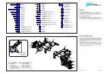
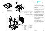
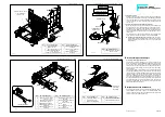
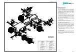
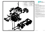
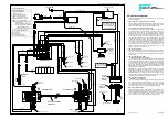
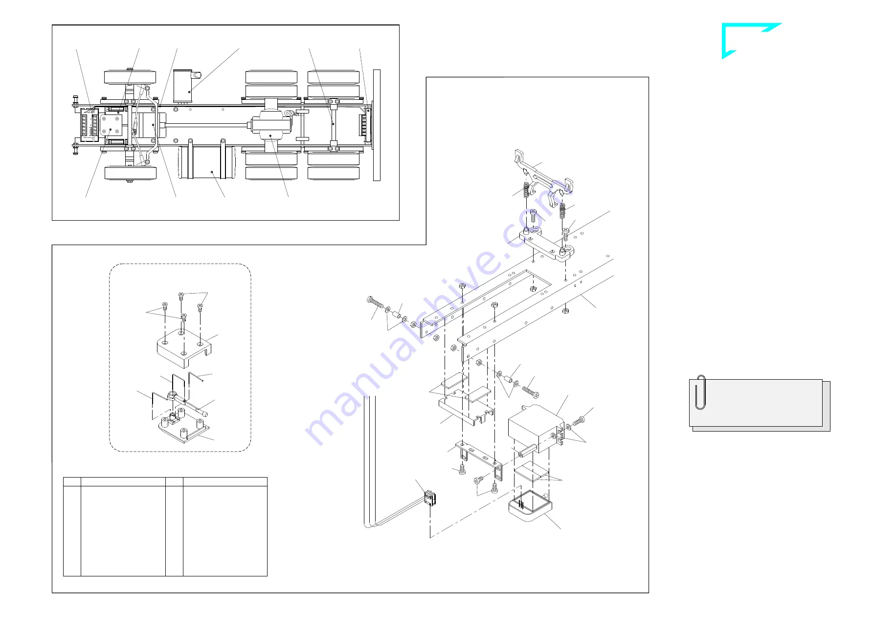
The illustration at the left shows the locations of the PCBs and the
routing of the ribbon cable beneath the frame. The cable will have to
be installed underneath the frame before the electrical devices are
installed in their entirety. The cable should run between the frame
and the axles, the fifth-wheel shaft and the screws used to affix the
tank. If the cable were to be laid later it would be necessary to disas-
semble some components already installed.
The best course of action is to read all the information on the electri-
cal system in Chapter 17 before you begin assembling the compo-
nents on the frame. This will give you an idea of which components
will be connected by cable.
V
`çãéçåÉåíë=~íí~ÅÜÉÇ=íç=íÜÉ==
Ñêçåí=Ñê~ãÉ=ëÉÅíáçå=
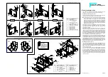
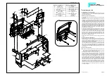
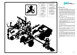
9.1 Fixing parts for the cab
Using each two nuts M3 to attach one screw 4, washer 13 and bush-
ing 26 onto the lower front holes on both sides of the frame 1388. At
a later stage of assembly (after the completion of all assembly
groups - see Chapter 16 - the front panel of the cab will be set
hereon.
Press the locking device 1029 into the base 1030 and set both pres-
sure springs 176 laterally between the pigots of these two parts. Ac-
cordingly to the illustration mount the base with screws 2 and nuts
M3 onto the frame. After adding the cab to the frame both noses of
the locking unit catch over those stopping devices mounted on the
rear panel and thereby secure the cab.
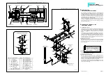
9.2 Mounting the servo unit
Accordingly to the drawing, use screws 57, washers 13 and bushings
1385 to fix the steering servo onto the servo supporting angle 760.
Use screws 2 and nuts M3 to attach the servo supporting angle un-
derneath the frame.
9.3 Mounting the PCB support
Use two adhesive pads 655 to affix the PCB support 723 behind the
servo supporting angle under the frame.
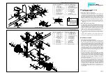
9.4 Assembling the blinker switch
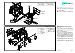
Slide two single-bent springs 721 into the corresponding holes and
slots in the base plate 720. Insert the double-bent spring 722 into the
two holes on the lever blinker switch 724 and then place the eye of
the lever over the boss on the base plate. The cover plate 719 is now
secured to the base plate with countersunk screws 564.
Attach the blinker switch with two adhesive pads 655 that way onto
the steering servo, that the clamp-type connector 929 lays closely on
the fore edge of the housing.
Components attached to the front frame section ill. 9
View from below showing the location of components mounted onto the frame ill. 8
Moment of torsion of the servo should
be at 30 Ncm. The servo supporting angle
will fit servos with the following data:
L x W x H: ........................41 x 20 x 38 mm
Gauge for screwing ....................48
±
2 mm
Qty.
No. Assembly part
8
--- Nut M3
6
2 Screw M3 x 8
2
4 Screw M3 x 16
8
13 Washer 3.2
2
26 Bushing 4 x 0.5 x 7
2
57 Screw M3 x 10
2
176 Coil spring for lever
4
564 Countersunk tapping
screw 2.2 x 4.5
4
655 Adhesive pad,
double-sided
1
719 Cover for blinker switch
1
720 Base for blinker switch
Qty.
No. Assembly part
2
721 Spring, single bent
1
722 Spring, double bent
1
723 PCB support, small
1
724 Lever for blinker switch
1
760 Servo angle 1, small
1
929 Clamp-type connector,
3-pole
1
1029 Cab locking device
ACTROS
1
1030 Cab base ACTROS
2
1385 Threaded bushing 18mm
1
1388 Frame ACTROS,
432mm
Assembly of blinker switch
Blinker switch Gear Speed controller Differential
B-80-6
Ribbon cable
from the switch
Steering servo
(not incl.
in the kit)
fully assembled
blinker switch
Front PCB Steering servo Ribbon cable Exhaust unit Rear axle Rear PCB
g
re
e
n
b
ro
w
n
w
h
it
e
B-80-5

