


Managing Network Interfaces
Rev 4.0
User Manual
56
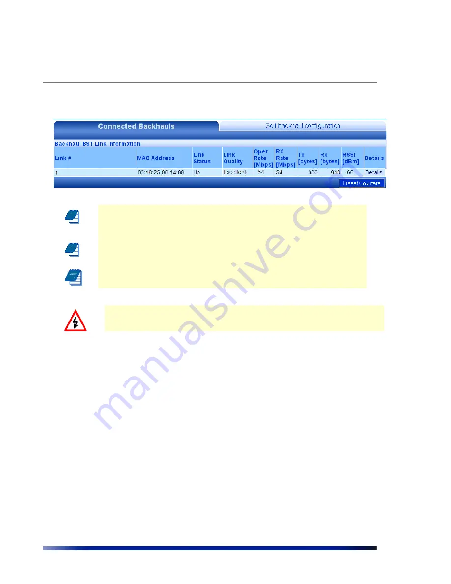
Figure 3.14
Backhaul BST Link Information page
Note:
To avoid Network loops, make sure there is no wired Ethernet
connectivity to the remote BST that closes a loop with the Ethernet
connectivity to the Central BST.
Note: All BST in the same cluster must be configured to the same
channel.
Note: Range in all cluster should be the same
W
ARNING
:
Do not connect between two Central BST; this may lead to loose the
connection between units.
How to initiate Channel Scan in Self Backhaul Mode:
Pressing scan button in the ACS page will initiate the scan process. During the process, the
system will reboot to Scan Mode, perform the scan and afterwards will automatically reboot
back to Operational Mode.
During scan mode the system will not be in operation, i.e. client will not be able to associate,
although beacons will continue to be transmitted.
How to return to Operational Mode:
The system will automatically return to operational mode with the previous selected channel
after the scanning.
During any time in which the system is not in operational mode, selecting channel from
"Operational channel" list-box and pressing reboot will return the system to operational mode
with the selected channel. Note that such operation is possible only on the Central BST (that
still has Ethernet backhaul. However, if the operational channel of the central BST changes,
make sure the same channel is selected on the remote BST (can be done if you wirelessly
connect to the remote BST).


