background image

1726 North Ballard Road, Suite 1 - Appleton, WI 54911 - 920.991.9082 

Technical Support 855.804.5774 - [email protected]

PTM30045-F

22 FEB 2018

W

E

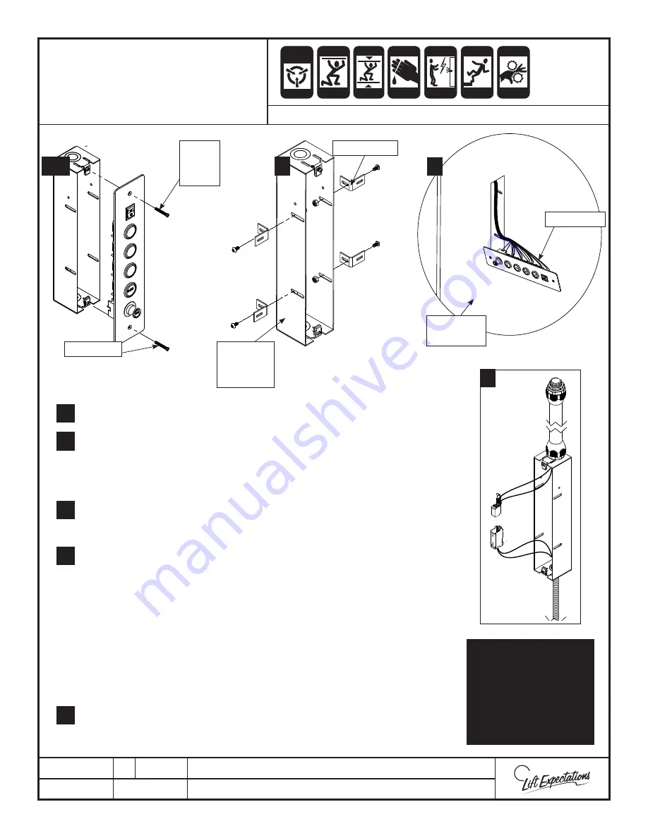
1  Remove screws from COP and place in a safe place.  

2.  Locate COP hole in the elevator car wall and measure the wall thickness. 

Place the COP brackets in position on the COP electrical box.  Off set the 
brackets from the front edge of the COP electrical box by the distance 
measured.  Fasten the (4) COP brackets to COP electrical box with the 


following provided hardware.


For elevator series 114, 021 and 022 

route slack cable fl ex into the  

bottom of the COP box and fasten.  Connect (2) slack cable plugs together 
inside the COP box. The 2x4 enclosure should hang below the elevator car.

4.  Slide COP cover plate through the COP hole in the elevator car wall.  

Be careful not to scratch any surfaces or pull out any factory wires.

5.  Place COP enclosure with secured brackets into COP hole and fasten to wall 

using the provided hardware. 

 Note: 


The installer may have to square off   the corners or weld spots of the 

COP hole in the elevator car wall to fi t the COP enclosure properly. While 
doing this verify the interior of the elevator car wall is not being damaged or 
accidentally making the COP hole larger than it should be.

  Verify that the provided screws do not pierce through the interior wall of 

the elevator car.   

6  Fasten COP cover plate onto COP enclosure with previously removed screws.

NOTE:

Some wires not shown 

for clarity.  Install prior 

to car wall installation.  

Slack cable plugs 

contained in the COP are 

only used for Series 114, 

021 & 022 units.

CAR

OPERATING PANEL

INSTALLATION

SERIES :

  008, 114 , 116, 118,  021,  022,  210

1, 6

2

CRUSH

HAZARD

CUTTING

HAZARD

CRUSH

HAZARD

CRUSH

HAZARD

CRUSH

HAZARD

CRUSH

HAZARD

ELECTRIC

HAZARD

FALLING

HAZARD

CRUSH

HAZARD

PINCH

HAZARD

ANTI- 

STATIC

ALERT

1.

4.

3

2.

4

3.

6.

COP

Cover

Plate 

COP Panel

Elevator

Car Wall


Brackets x4

Screws x2

COP

Electrical 

Box 

Page 33

Summary of Contents for Excelevator 114 Series

Page 1: ...ructions Excelevator Elevator Series 114 950 1 000 lbs PMI114 V 30 March 2018 1726 North Ballard Road Suite 1 Appleton WI 54911 Phone 920 991 9082 Fax 920 991 9087 Technical Support 855 804 5774 www waupacaelevator com ...

Page 2: ......

Page 3: ...unt Telephone Jack 34 Handrail Installation 35 Framlees Car Assembly 36 38 Stabilizer Bracket Installation 39 Steel Tape Installation 40 Description P a g e Slack Rope Safety Wiring 41 Modular Wiring Car Top Layout 42 Emergency Light Installation and Fuse Installation 43 Car Top Modular Wiring 44 Tape Reader Driver Board 45 LED Light Installation 46 LED Light Wiring without battery backup 47 LED L...

Page 4: ...ration of this unit Read them carefully before beginning installation Inspect for visible signs of damage or missing parts BEFORE beginning installation The final check list indicates all components included with this order Work by others to include but not limited to the hoistway construction supports for guide rails and an electrical fused disconnect to control panel Do not expose electrical com...

Page 5: ...F CALL DEALER FOR SERVICE OR AN ELEVATOR SERVING COMPANY DO NOT REMOVE OR COVER THIS SIGN L 006432 B 1 Close hoistway door and close elevator gate 2 If keylock is provided insert key in lock and turn to ON 3 Press desired floor on the car operating panel 4 Once stopped at landing open gate 5 Open door and exit elevator 6 Close the gate 7 Securely close hoistway door 8 Should elevator fail to opera...

Page 6: ...ce this hose Installed by ______________________________ Date Installed ______________________________ PER ASME A17 1 REPLACE HOSE EVERY 6YEARS OR SOONER IF REQUIRED BY LOCAL JURISDICTION L 006430 B Minimum Bend Radius 4 80 in Factory Test Pressure 3700 PSI Factory Test Date _______________ Inspection of hose to occur annually or as directed by local jurisdiction Visual Inspection Check for weepin...

Page 7: ...ks Material to Close Off Hoistway Chain Hoist All Purpose Grease Wood Glue Paraffin Wax Temporary Supports for car Thread Locker Rags or Toweling Hand Tools Socket Wrench Set Allen Wrenches SAE Metric Utility Knife Cable Cutter File Set Flashlight Needlenose Pliers Rubber Mallet Hack Saw Scissors Set of Screw Drivers flat Phillips Vise Grips Wall Board Roll Lifter Pre set Interchangeable Head Torq...

Page 8: ...accepted after 45 days All RMA s have a 45 day open date for receipt by Waupaca Elevator 8 All replacement part orders will be invoiced upon shipping and will not be credited until the original part s have been returned to the factory prepaid no C O D s will be accepted a Credit will be issued if evaluation proves components or to have failed within our warranty period b Credit will not be issued ...

Page 9: ...ooting Tips 1 Take notes as you troubleshoot for future reference 2 Visually inspect component s 3 Check for loose wires and broken contacts 4 Be familiar with your multimeter 5 When testing fuses take them out of the circuit failure to do so may result in a false reading 6 When checking for voltage do not check to ground For Technical Support Call 1 855 804 5774 CRUSH HAZARD CUTTING HAZARD CRUSH ...

Page 10: ...Line Rail Backing Chain hoist attachment point Strongly Recommended Hoistway Dimensions FAILURE TO VERIFY these dimensions with the drawings on site may drastically INCREASE the amount of TIME spent on the job Other Hoistway Verifications Verify these other hoistway dimensions and specifications before proceeding with installation of elevator 1 2 3 4 5 A Machine room location dimensions if applica...

Page 11: ...il brackets are provided then reference the illustration for the required 4 slots as fastening points into the backer Note If conversion rail brackets are provided follow instructions below if not provided proceed to the general rail bracket page WARNING These drawings depict sample construction only It is the responsibility of the installer contractor or engineer to design and specify structural ...

Page 12: ... with appropriate hardware Ensure rail brackets are level Shim as required Continue to fasten remaining rail brackets except the jack and pedestal brackets onto wall The jack and pedestal brackets will be installed during rail installation Locate the positions for both the jack and pedestal brackets clamp each bracket onto the bracket below their designated mounting height DO NOT FASTEN PEDESTAL O...

Page 13: ...d for verifying the hoistway dimensions and for locating and marking VERIFY ALL FASTENERS ARE SECURE ASSEMBLE MAIN RAIL PER FIELD DRAWINGS Place level on bracket align side of bracket to plumb line and mark 4 holes Drill 4 appropriately sized pilot holes Realign bracket before fastening to wall with appropriate hardware shim as required Continue fastening all rail brackets onto the wall until comp...

Page 14: ...rs 2 1 2 13 x 1 1 2 bolts 2 1 2 13 nuts 2 1 2 flat washers 5 Hand tighten both fish plates to lower rails with 8 1 2 13 x 1 3 4 bolts 8 1 2 lock washers 16 1 2 flat washers 8 1 2 13 nuts 6 Set upper rails into place one at a time and hand tighten fish plates to both upper rails with the following hardware 8 1 2 13 x 1 1 2 bolts 8 1 2 lock washers 16 1 2 flat washers 8 1 2 13 nuts Check for plumb w...

Page 15: ...to jack installation for PRV positioning Remember DO NOT CROSSTHREAD Step 7 Fasten top sleeve to jack bracket If a second jack bracket is provided fasten to bottom sleeve reference field drawings for bracket locations Step 8 Insert gland assembly into top sleeve Step 9 Fasten flange assembly to top sleeve with socket head cap screws Refer to jack installation for overflow relief positioning Step 1...

Page 16: ...eded to maintain mechanical clearances 7 Plumb and securely fasten jack to jack brackets by tightening U bolt Note Compress rubber strap approx 1 8 do not over tighten 8 Screw tube fitting into weep hole on the jack crown overflow relief with elbow facing downward direction 9 Press tube over tube fitting firmly until tube is fully secure run down jack and into drip jug do not obstruct any part of ...

Page 17: ...oving the following 2 3 8 16 x 1 1 4 bolts 4 3 8 flat washers 2 3 8 16 nylock nuts Remove bolt from top of jack and fasten the jack mounting plate to the jack with the previously removed bolt M30 x 3 5 bolt Verify jack bolt is secure Set ram header into place and fasten to the jack mounting plate with the previously removed hardware 2 3 8 16 x 1 1 4 bolts 4 3 8 flat washers 2 3 8 16 nylock nuts Us...

Page 18: ...6 from the face of the equipment The height of working space in front of equipment must be a minimum of 6 1 2 ft or height of the equipment whichever is greater per NEC Code 30 minimum width or the width of the equipment Per NEC Code 110 26 Clear Working Space The working space required by this section must be clear at all times Therefore this space isn t permitted for storage When normally enclos...

Page 19: ...RICITY CONTROLLER INSTALLATION AND WIRING SERIES 114 116 Per NEC Code 110 26 Continued 3 Height of Working Space Headroom The height of the working space in front of equipment must not be less than 6 measured from the grade floor platform or the equipment height whichever is greater Other equipment must not extend more than 6 into the controller working space Additional Notes A lockable service di...

Page 20: ...the gasket pipe and pipe fitting into the valve assembly 4 Route the hydraulic hose if supplied between the piping from the jack to pipe connection on the top of the power unit Fill in the blanks on the flexible hose tag route hose per ASME A17 1 CSA B44 and local code Note The hydraulic hose will shrink when pressurized Be sure there s slack between the piping and the hydraulic power unit to acco...

Page 21: ...opriate hardware Loosen the screw and open cover Verify the normally closed contacts with a multi meter Wire to the previously verified normally closed terminals All wiring must meet N E C and local codes Note Do not over tighten terminals Terminals should be torqued to 7lb in max Verify the operation of the final limit switch Replace cover and refasten screw Adjust as necessary the final limit sw...

Page 22: ...ate pendant nut clockwise to fasten onto receptacle Step 5 Turn UPS ON Step 6 Turn PLC toggle switch to the ON position TO USE Step 1 Turn OFF all power to the unit at the controller disconnect and battery Step 2 Turn PLC toggle switch to the OFF position Step 3 Unplug UPS battery Step 4 Rotate pendant nut counterclockwise and remove from receptacle TO DISCONNECT WARNING VERIFYTOP FINAL AND BOTTOM...

Page 23: ...from the jack by running pump Refer to pendant control page 4 Once fluid begins to seep out of bleeder stop the pump Securely fasten the bleeder bolt in the jack sleeve Once complete clean up the seepage 5 Using the pendant control project piston to proper distance and continue with shackle installation Refer to field drawings INFORMATION ON PISTON PROJECTION By definition Piston Projection is the...

Page 24: ...s Remove the bolts from the safety actuation links on both side of the slings and swing clear of the square rod Note Safety actuation paddle will rotate freely Assemble shackles in sling with provided hardware rubber pad springs plastic bushings washers jam nuts and cotter pin Place the shackle nuts initially at 3 from the bottom of the shackle rod Loosen the eccentric rollers and adjust to maximi...

Page 25: ...ts 20 1 2 flat washers 10 1 2 lock washers 10 1 2 13 nuts Place top cross members into position with the sling uprights and hand tighten with the following hardware FACE OF THE CROSS MEMBER 8 3 8 16 x 3 4 bolts 8 3 8 16 serrated flange nuts TOP OF UPRIGHTS 4 3 8 16 x 1 bolts 4 3 8 16 serrated flange nuts Place 4 gibbs into position on the sling uprights and hand tighten into position with the foll...

Page 26: ...te on the main arms of the base sling To verify the bolt plates bolts are touching the sling extension if not the 3 3 8 square washers will be needed If the bolts are touching you do not need the 3 3 8 square washers Place the side arm on the bolts Replace the previously removed hardware SLING EXTENSION INSTALLATION 1 1 2 3 3 FALLING HAZARD CRUSH HAZARD PINCH HAZARD CRUSH HAZARD CUTTING HAZARD BOL...

Page 27: ...es By loosening and or removing the hardware adjusting sliding the side arm and then re tightening Adjust front extension angle by loosening removing provided hardware Place the front extension angle in the desired position Replace and re tighten the provided hardware Following the rules from step 4 Test fit the sling extension on the sling base Determine if the elevator car pads are needed Make a...

Page 28: ...OPES PROPER HANDLING OF WIRE ROPE OPEN KINK CLOSED KINK STARTING TO LOOP KINKED BY TENSION GENTLY HOLD DOWN ONE END CAREFULLY UNCOIL ROPE WHILE WALKING DO NOT TWIST OR KINK THE ROPE SWEDGE If swedge is not provided with your unit use the wire rope ends DANGER FAILURETO HEED MAY RESULT IN DAMAGE OR INJURY Series ALL CRUSH HAZARD CUTTING HAZARD CRUSH HAZARD CRUSH HAZARD CRUSH HAZARD CRUSH HAZARD FAL...

Page 29: ...use damage to the hoistway components or injury to the installers Note Verify wire ropes are not crossed at any point throughout their complete length Route the wire rope closest to the rail wall through the shackle socket closest to the rail wall in the pedestal base Create a loop by routing wire rope back through the shackle socket Insert wedge into the newly created loop Pull the wire rope and ...

Page 30: ...e ropes are not crossed at any point throughout their complete length Route the wire rope through the shackle socket closet to the rail wall while pulling down on the wire rope to seat the shackle tightly in the pedestal base Loop the wire rope up back through the shackle socket while continuing to hold the tension on the wire rope Insert the wedge into the newly formed loop and pull on the dead e...

Page 31: ...the eccentric rollers until there s a 1 32 gap between the rail and the safety The eccentric wheels must stay in the same plane with each other Verify this with the dimple on the end of the roller axel Tighten the roller Rotate the paddle into place and reinstall the previously removed hardware through the safety actuator links and square tube on both sides of the sling Insert the bolts from the t...

Page 32: ...e clamp at a perpendicular angle and secure wire ropes together Reference Proper Handling of Wire Rope page TEST SAFETIES FOR PROPER OPERATION BEFORE CONTINUING INSTALLATION Raise jack to full length of travel and check oil level in the pump with attached dip stick Ensure oil level is maintained between the indented marks provided on stick Note It s recommended the hydraulic oil level be checked a...

Page 33: ...es 5 Place COP enclosure with secured brackets into COP hole and fasten to wall using the provided hardware Note The installer may have to square off the corners or weld spots of the COP hole in the elevator car wall to fit the COP enclosure properly While doing this verify the interior of the elevator car wall is not being damaged or accidentally making the COP hole larger than it should be Verif...

Page 34: ...efore it is released to the customer 1 Drill 1 opening in car wall 2 Mark and drill 4 1 16 pilot holes 3 ALL OTHER LIST SERIES Run wire from the wall mount telephone jack red green wires to the phone PH terminals in the car top box Do not route over high voltage wires 4 Connect shielded travel cable wires to phone PH terminals in the car top box 5 Connect the other end of the shielded pair to the ...

Page 35: ...pre drilled holes and fasten snuggly in place with set screws facing downward Then loosen the set screws 2 Align the edges of the standoff so its level Verify the seams are free of gaps Securely fasten in place 3 Align handrail with aluminum studs and press into position on wall Verify a tight fit between handrail and handrail spacer 4 Securely fasten 2 1 4 20 x 1 4 set screws in place HANDRAIL IN...

Page 36: ...e Insert provided dowels into pre drilled holes along the top of the walls wall B or rail wall will have fasteners already attached to the bottom Insert dowels into pre drilled holes along the top and bottom of post s and pocket s if provided and opposing wall if opposite opening layout Warping before installation may occur To correct the warping place provided shims between the outside wall and t...

Page 37: ...l cars except the Designer hang past the car floor Before fastening floor to sling be sure to allow enough clearance between car floor and sling upright Drill at least 4 holes and bolt floor to sling using provided hardware Verify clearance between car floor and all hoistway walls Refer to field drawings for details Insert wall B or rail wall with fasteners onto floor A pins and slide into place d...

Page 38: ... at the connecting corner and connect the pins in wall E into the fasteners in wall D Drive dowels from floor A into wall E with a rubber mallet to prevent walls from moving or sliding Set ceiling F onto walls B C D and E with dowels Use rubber mallet to drive dowels through the ceiling and into walls Fasten ceiling first then floor panel to walls with provided hardware in pre drilled locations Ve...

Page 39: ...ock nut Otherwise noise will result when the tape reader binds with the steel tape Fasten assembled tape reader and tape reader bracket from step 5 to bottom left cross member using 1 3 8 16 serrated flange nut Square the elevator car to the floor landing opening Mount the car stabilizers with 2 lag screws one per bracket Verify elevator car clearances and openings to other floor landing openings ...

Page 40: ...1 1 4 20 x 3 4 elevator bolt 1 1 4 flat washer 1 1 4 lock washer 1 1 4 20 nut Feed tape through tape reader Attach and fasten steel tape to the bottom bracket before clamping the tape bracket to the rail Use the following hardware 1 1 4 20 x 3 4 elevator bolt 1 1 4 flat washer 1 1 4 lock washer 1 1 4 20 nut Use the steel tape to locate the bottom bracket on rail Pull tape down tightening steel tap...

Page 41: ...OT pierce through the interior car walls Connect the two connectors inside the electrical box and Fasten 2 x 4 cover onto box with previously removed hardware Note Verify the conduit will not be damaged by any object during the length of the elevators travel and will also not to be damaged when the sling is sitting on the pit floor or mechanical stops 4 Verify the switch contacts change state when...

Page 42: ...ess to car top box with the connectors and plug them into appropriate receptacles reference Tape Reader Driver Board Car Top Modular Wiring schematics and Auto Gate manual If provided plug the auto gate plug s into plugs based on gate usage below AG1 Primary Gate AG2 Secondary Gate AG3 Tertiary Gate Anchor car top box and LED light covers with provided hardware Install travel cable COP phone and s...

Page 43: ...ior car wall and ceiling to determine location 6 Remove light and mark wire location on wall or ceiling depending on chosen mounting position and drill 1 4 hole through on mark Verify the wire length is long enough to reach the alarm box 7 Feed emergency light wires through 1 4 hole to alarm box and through the bushing into the alarm box 8 Fasten light fixture into place with appropriate hardware ...

Page 44: ...ES 008 114 115 116 118 021 022 210 311 511 1 2 3 4 5 7 8 9 10 11 12 13 14 15 16 17 18 19 20 21 22 23 24 6 Light Relay Tape Interface Receptacle Board Receptacle 1 Travel Cable Plugs 13 Gate Switch 2 2 14 Gate Switch 3 3 15 Light 1 4 16 Light 2 5 N A 17 Light 3 6 Car OperaƟng Panel Plugs COP 18 Light 4 7 19 Bell and E Light 8 20 Emergency Stop 9 AutomaƟc Gate 1 21 PosiƟon Indicator 10 AutomaƟc Gate...

Page 45: ...AZARD FALLING HAZARD CRUSH HAZARD PINCH HAZARD ANTI STATIC ALERT To TheTap e R e a d e r Top of Plug Verify the Wire Colors Tape Reader Interface Board Connectons Plug White wire fits to the first pin Car Top Board Standard Circuit Board Tape Reader Interface Circuit Board Green Tan Grey Violet Blue Pink Yellow Orange Red Brown Black White Series 008 114 115 116 118 021 022 210 311 511 24 24 NA DZ...

Page 46: ...r the desired route has been laid out Cut the connector off the unused end of the LED extension cord Next feed it through the conduit until it reaches the power supply If the LED extension cord needs to be shortened remove it from the conduit and cut to the desired length Finally feed the wire back through the conduit Note Before cutting verify you re cutting the right end of the LED extension cor...

Page 47: ...N IN THIS DIAGRAM ALWAYS CONNECT ALL 3 WIRES RED BLACK YELLOW EVEN IF DIMMING IS NOT REQUIRED TO TURN LIGHTS ON AND OFF SIMPLY ENERGIZE OR DE ENERGIZE THE 120 240V AC INPUT TO THE EL2 POWER BOX ATTENTION REMOVE ALL JUMPERS AS REQUIRED OUT OF THE LED LIGHT CONTROLLER BOX CRUSH HAZARD CUTTING HAZARD CRUSH HAZARD CRUSH HAZARD FALLING HAZARD ANTI STATIC ALERT WITH OUT BATTERY BACK UP WIRING STANDARD 3...

Page 48: ...d national local codes Verify that all LED lights work and adjust the dimmer to desired brightness Secure the LED Light covers and power supply to the ceiling of the elevator car with provided hardware When the installation is complete press the test switch to test light operation Allow up to 10 hours for a battery to fully charge before testing 5 WITH BATTERY BACK UP WIRING OPTIONAL 1 2 4 3 WARNI...

Page 49: ...nd gate upright while maintaining the gate stack in the correct orientation locate handle on the strike side and slide the track onto the wheels Lineup the wheels properly in the track grooves Be careful not to slide the wheels in sideways If necessary reference field drawings for correct gate orientation 4 Slide top of gate with gate track in place on the car ceiling in original factory location ...

Page 50: ...the marked edge and the previous step needs to be repeated 10 Once the gate stacks properly re extend the gate and fasten the mounting panel with 2 6 x 1 1 2 flat head screws between the first 2 screws evenly splitting the distance 11 Dry fit the gate strike jamb against the opposite wall of the stack The strike jamb needs to be centered with the top gate track and the floor track groove Slide the...

Page 51: ...PAGE INTENTIONALLY LEFT BLANK Page 51 ...

Page 52: ...actuator arm onto the gate lead post with the provided hardware Verify the gate switch is the correct hand for the gate Remove the cover of the gate switch and place the cover and screws aside and fasten the gate switch to the gate switch bracket with provided hardware With the gate closed fasten the assembled gate switch and bracket to the top of the elevator car with provided hardware Verify the...

Page 53: ...ing over and under travel to verify that the traveling cable moves gracefully and does not get caught on any part of the elevator car or any item mounted in the hoistway Verify as it moves that it does not pull on the strain relief anchor points Adjust as necessary Note Ensure traveling cable can not be crushed when resting on mechanical stops 4 Route travel cable to the controller All wiring must...

Page 54: ...4F 24 EZ1 5 5F 25 LD 6 6F 26 LU 7 FC 27 DZ 8 1A 28 NOT USED 9 2A 29 24 10 3A 30 24 11 4A 31 AG1 12 5A 32 AG2 13 6A 33 AG3 14 AC Purple 14 Gauge AUX 15 ESTOP White 14 Gauge NEUT 16 SC Black 14 Gauge LT 17 LITE Green 14 Gauge GRD 18 GATE Shielded Red PHONE 19 EZ6 Shielded White PHONE 20 EZ5 CRUSH HAZARD CUTTING HAZARD ELECTRIC HAZARD FALLING HAZARD PINCH HAZARD STATIC HAZARD ELECTRICITY TRAVEL CABLE...

Page 55: ... and local codes Use 18 gauge stranded low voltage wiring other than provided harnesses Refer to proper pages for individual component installation If the unit that you are working on is equipped with EMI III s be sure the jumper is installed between DC and DL in the controller CRUSH HAZARD CUTTING HAZARD CRUSH HAZARD CRUSH HAZARD CRUSH HAZARD CRUSH HAZARD ELECTRIC HAZARD FALLING HAZARD ANTI STATI...

Page 56: ...Wire hall station per schematic Fasten hall station plate onto box with provided hardware Do not allow any of the wires to become cut or pinched by the cover Car Here Light Hall Station Terminals Controller Terminals Call Button Hall Station Terminals Controller Terminals COM N O N C LMP COM N O N C LMP COM N O N C LMP COM N O N C LMP EC EMI 1 EMI 6 N O COM FC 1F 6F IU1 IU2 TB1 LMP TB2 LMP TB1 TB2...

Page 57: ...ng appropriate hardware to mount pit stop switch in the hoistway 18 above the lowest floor landing and within reach from the lowest floor hoistway door Note If the lowest landing has 2 or more means of access you may need an additional stop pit switch so a switch can be easily accessed from each access point Per code A17 1 when the pit exceeds 1700mm 67 in in depth an additional stop pit switch is...

Page 58: ...r Leveling Magnet 7 LONG Controls elevator leveling Initiates floor count Enables PLC to recognize door zone Initiates releveling LEGEND MAGNETS THEIR FUNCTIONS EZ1 MAGNET EZ6 71 3 4 74 Above floor level is initial setting adjust as required Note Measurements are based off a 7ft car Height may vary C L C L C L C L C L C L 1 2 GAP 1 1 2 Note For fine adjustments of floor height move all the magnets...

Page 59: ...locations previously marked in step 2 with a 3 32 drill bit x 1 1 4 deep pilot hole Place toe guard into position established in step 1 Verify both toe guard edges line up with the outside wall edges the top of the toe guard lines up with the bottom of the car sill and the hole patterns align with the pilot holes drilled Fasten toe guard onto car floor with a 6 x 1 1 4 coarse screw per each hole N...

Page 60: ...he controller A Insert male controller plug into UPS battery backup surge protection side B Insert male battery backup plug into controller female plug 3 Turn toggle switch to the ON Position 4 Turn UPS ON 5 If the unit that you are working on is equipped with EMI III s be sure the jumper is installed between DC and DL in the controller Note The battery back up is ONLY used for the emergency decen...

Page 61: ... Definitions RUN Run Contactor Output UP Up Contactor Output HSV High Speed Valve Relay DV Down Valve Relay LR Cab Light Automatic Timer Relay SV Up Low Speed Valve Relay EMI 1 6 EMI Outputs 1 6 A Floor Acknowledgement Lights in the COP AG1 Autogate 1 AG2 Autogate 2 AG3 Autogate 3 DF Door Fault Input I 0 0 0 1 0 2 0 3 0 4 0 5 0 6 0 7 IndicaƟon Gate Estop DC DL LPS PS TF OVLD Output Q 0 0 0 1 0 2 0...

Page 62: ...the homing feature push and hold buttons 1 2 simultaneously until they light Continue to hold 1 2 until the lights go out and release Hydraulic Exercise Programming The hydraulic exercise program runs the elevator every 2 weeks if the elevator is idle This program is turned ON when the elevator is shipped Disabling Enabling the Exercise Program Instructions Call the unit to the second stop tape re...

Page 63: ...ure the gate contacts are not welded At a landing the door close and gate contacts must open at least once If just the gate contacts open the unit will be able to run just 4 times To return to normal operation open and close both the gate and the hoistway door Then the elevator will respond to calls To reset elevator program the gate switch contact must be broken and recontacted to resume proper f...

Page 64: ...1 AG2 AG3 Gray square indicates AG programmed to open PRESS 7x s NOTE Unit will not accept floor calls with SW1 in closed position Reference chart for number of times to push the button Flip SW1 to OPEN POSITION TO END this floor s programming NOTE Unit will not accept floor calls with SW1 in closed position Move Elevator to Any Other Desired Floor and Repeat PRESS 1x s PRESS 3x s PRESS 2x s PRESS...

Page 65: ...erride 6 Pressure Gauge Shutoff Screw 7 Manual Lowering Min Pressure Adjustment 8 Pressure Balance 9 Down Speed Adjustment 10 Hand Pump Pressure Relief Valve Adjustment 11 Hand Pump Air Bleeder 12 Inspection Gauge Fitting VP Pressure Valve VMD Down Solenoid Valve VML Full Speed Solenoid Valve VRFP Auxiliary Down Speed Control Valve TROUBLESHOOTING TIP When energized the coil stem becomes magnetize...

Page 66: ...and run the unit to ensure working pressure is less than 740 psi A If the pressure while under full load exceeds 740 psi contact technical support before proceeding any further B Take note of the pressure during this step this is the working pressure of this particular elevator All elevators will have a slightly different working pressure due to head losses resulting from piping configurations and...

Page 67: ... the valve does not set during normal operation A If the valve sets during normal operation adjust the set screw as necessary 7 Thread the cap nut back over the set screw and tighten against the jam nut TEST THE PIPE RUPTURE VALVE Ensure oil is at room temperature before testing the valve 1 Turn Down Speed Override 5 clockwise until fully closed Lower elevator to actuate pipe rupture valve A Ensur...

Page 68: ...terface board and related wiring Elevator Stops Short of Top Floor and Returns to 1st Floor with Car Lights Blinking Low oil time out fault 90 seconds Check oil level and oil temperature Check for leak in pump assembly pump to jack plumbing Check HSV Elevator Travels Down Only Up contactor not pulling in Check up output on PLC and UP contactor No incoming power Check up output on PLC and UP contac...

Page 69: ... running Improper magnet placement Check magnet placement Travels Past Floor then Relevels Leveling speed is too fast Adjust leveling speed HSV Relay is welded Will Not Travel Down Pipe rupture valve is out of adjustment Check pipe rupture valve and adjust Check pressure gage to determine if pipe rupture is working Elevator stops just outside of the door zone while leav ing the floor landing EMI I...

Page 70: ...s the slow down when coming to a floor I8 6 Level up sensor Maintains the cars position at the floor I8 7 Level down sensor Maintains the cars position at the floor I9 0 EZ 1 Sensor Lights when at the first floor triggers EMI1 output I9 1 EZ 2 Sensor Lights when at the second floor triggers EMI2 output I9 2 EZ 3 Sensor Lights when at the third floor triggers EMI3 output I9 3 EZ 4 Sensor Lights whe...

Page 71: ... Q8 4 EMI 5 Lights when the car is at the fifth floor and EZ 5 input is on Q8 5 EMI 6 Lights when the car is at the sixth floor and EZ 6 input is on Q8 6 DF Indicates Door Fault Condition Q8 7 SCR Reset On First Scan Resets SCR Q9 0 First floor acknowledge light Lights when a first floor call is engaged Q9 1 Second floor acknowledge light Lights when a second floor call is engaged Q9 2 Third floor...

Page 72: ... Supply CR1 SW1 F32A 24 24 24 24 2F 1F Phone Phone CR1 4F 6F 5F DZ FC LD LU SP1 SC SP2 GATE ESTP LITE AG2 AG1 1A AG3 3A 2A 4A 6A 5A AC EZ2 EZ1 EZ3 EZ5 EZ4 EZ6 PS1 TF1 PS2 DC TF2 DL DC DL IU2 IU1 RS1 EMI1 EMI3 EMI2 EMI5 EMI4 EMI6 DF EC LPS1 LPS2 DV SV HSV VC VC T1 T2 24 24 24 24 24 24 NEUT NEUT NEUT COM L2 L1 RS2 3F SCR HSV DV SV PF SCR HSV DV SV PF F13A 24 F24A 24 GRD RUN UP OVLD PLC EXP MODULE EX...

Page 73: ...ng gland for leakage Check pipe rupture valve for leakage Check wear and leakage of hose pipe Check pit bucket and empty Clean and lubricate rollers C ON T R OLLER Check contacts for excessive burning and clean Check and test battery device Check fuses holders and replace if necessary GA T E Check gate operation Check and clean gate operator switches C A R Check alarm bell system Check emergency s...

Page 74: ...______________________________________________ _______________________________________________________________________________________ _______________________________________________________________________________________ _______________________________________________________________________________________ _______________________________________________________________________________________ _...

Page 75: ... GMV serial number tag Maintence Controlled Sheet Located in the Installation Manual IN THE MACHINE ROOM Fuses Remove all temporary jumpers Check all fasteners Leave area equipment clean Slack Cable Switch Re verify Wire Rope Tension Verify LPS setting is correct Verify hydraulic oil is at proper level Verify there are no leaks in the system Interlock Key stored correctly Controller Door Storage P...

Page 76: ......

Page 77: ......

Page 78: ...PMI114 V 30 March 2018 1726 North Ballard Road Suite 1 Appleton WI 54911 Phone 920 991 9082 www waupacaelevator com ...

Reviews: