


16
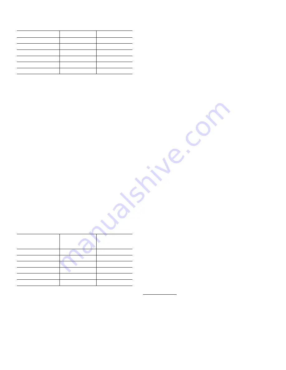
Table 1 Injector Order Information
Part Number
Color
Tank Diameter
KC11V3010-1D
Red
9"
KC11V3010-1E
White
10"
KC11V3010-1F
Blue
12"
KC11V3010-1G
Yellow
13"
KC11V3010-1I
Orange
16"
KC11V3010-1K
Lt Green
21"
Refill Flow Control Assembly
The refill flow control assembly consists of a refill flow elbow, refill
flow control retainer assembly, refill flow control, poly tube insert, and
nut assembly. The refill flow control retainer fits in the refill elbow. The
refill flow control retainer houses the refill flow control, which controls
the flow rate when the regenerant tank is being refilled. The refill
flow control is a flexible washer-like part with a small orifice and a
precision-molded contour that delivers a steady 0.5 gpm regenerant
tank refill rate at varying inlet pressures. Refill is accomplished with
treated water.
The refill flow control assembly is installed in an easy to access
refill elbow located on top of the control valve. The refill flow control
assembly is attached to the control valve with a locking clip. The
locking clip allows the elbow to rotate 270 degrees so the outlet can
be orientated toward the regenerant tank.
Drain Line Flow Control/Fitting
The drain line flow control assembly includes a drain line flow control
and a fitting. The drain line flow control allows proper media bed
expansion by regulating the flow rate to the drain.
The drain line flow control is a flexible washer-like part with an orifice
and a precision molded contour. The flow rates are within ±10% over
the pressure range of 30 to 125 psi. The flexible washer-like parts
are identified with three numbers, which correspond to the flow rate
in gallons per minute. See Table 2.
The drain line flow control and fitting are located on top of the control
valve and replaceable without the use of special tools.
Table 2 Drain Line Flow Control (
3
⁄
4
" Fitting)
Part Number
Number on
Backwash
Fitting
Flow Rate
GPM
KC11V3162-022
22
2.2
KC11V3162-027
27
2.7
KC11V3162-042
42
4.2
KC11V3162-053
53
5.3
KC11V3162-075
75
7.5
KC11V3190-110
110
11.0
The drain line flow control can be installed in the standard
1
⁄
4
" drain
line elbow, which accommodates
5
⁄
8
" poly tube or
3
⁄
4
" NPT drain line
connections. The optional nut and poly tube insert for the
3
⁄
4
" drain
line elbow is designed for use with flexible poly tube only. The
3
⁄
4
"
drain line elbow can be rotated 180 degrees so the outlet can be
orientated to the nearest drain. The same retainer is used for all drain
line flow controls for the
3
⁄
4
" fitting.
Water Meter or Meter Plug
The water meter is installed on the outlet side of the control valve.
The water meter uses a turbine to total gallons of treated water. The
turbine rotates with the flow of water and reports its rate of rotation
through Hall-effect 8 circuitry to the printed circuit (PC) board.
This rotation permits the PC board to record the total volume of
treated water and the flow rate. The small centrally located magnet
is shielded from water, which reduces substantially iron-fouling
problems with the turbine. The turbine is accurate to within ± 5%
over a wide operating flow rate range (0.25 gpm up to control
valve maximums) and has a very low pressure drop. Water used for
regeneration is not metered. If the control valve is set to prefill the
regenerant, water used between the prefill cycle up to the start of the
regeneration cycle is metered. If the control valve is in regeneration
mode (such as a backwash cycle) and there is a water demand, that
water usage is not metered.
When facing the front of the control valve, the water meter is
positioned on the left-hand side of the control valve. Allow sufficient
clearance to clean and repair the water meter without disconnecting
the plumbing or disassembling any other parts of the control valve.
A unique feature of this control valve is the ability to display actual
water usage for the last 63 days. The value is initially stored as "_"
because it is unknown. As days pass values are stored as “O” for
no flow or the actual number of gallons. The counting of the gallons
starts at the regeneration time. If no regeneration time can be
set (that is, when the valve is set for immediate regeneration), the
counting of gallons starts at 12 a.m. Day 1 is yesterday, day 2 the
day before yesterday, and so on. As new values are added the oldest
history disappears.
Another unique feature is that the valve automatically calculates a
reserve capacity when set up as a softener with Gallons Capacity
set to AUTO. The reserve capacity for a given day of the week is the
middle value stored for the last three non-trivial water usages (that
is, less than 20 gallons per day) in 7-day intervals, which is then
adjusted either upward or downward depending upon the difference
between today’s water usage and the estimated reserve capacity.
Installation Fitting Assemblies
The installation fittings are used to connect the optional bypass or
the control to the plumbing system. There are four installation fitting
assemblies available.
• 1" NPT elbow
•
3
⁄
4
" and 1" PVC solvent weld elbow fitting
• 1" straight brass sweat fitting*
•
3
⁄
4
" straight brass sweat fitting*
Both elbow fittings have a unique drill-out feature to allow a
1
⁄
4
" NPT
connection to the inlet and/or outlet which can be used for an RO
feed, test ports, pressure tap ports, or other apertures.
The installation fitting assemblies are sold in pairs and consist of
2 fittings, 2 nuts, 2 split rings, and 2 O-rings. The installation fitting
assemblies and the bypass valve are sold separately from the
control valve.
Note: Some semiconductor materials exhibit a phenomenon in the presence
of a magnetic field that is adaptable to sensing devices. When a current is
passed through one pair of wires attached to a semiconductor, another pair
of wires properly attached and oriented with respect to the semiconductor
develop a voltage proportional to the magnetic field present and the current
in the other pair of wires. Holding the exiting current constant and moving a
permanent magnet near the semiconductor produces a voltage output pro-
portional to the movement of the magnet. Hall-effect devices provide a high-
speed response, excellent temperature stability and no physical contact.
*Has not been tested for compliance with California Proposition 65 so this fit-
ting should not be installed in California.


