background image

10

System Installation

  7*.  Connect the cold water supply to the inlet port of the water 

softening system’s control valve(s). When constructing the 

supply line, install an inlet water isolation valve and plumbing 

union fitting  (user supplied) in the supply line of each control 

valve and close the isolation valve. The union fitting(s) should be 

located between the isolation valve and the systems inlet port.

  8*.  Install an inlet water sample port in the supply line and close it.
  9*.  If risk of vacuum exists, install Watts # 0556031 vacuum 

relief valve in the supply line to protect the system against 

vacuum damage.

10*.  Connect the outlet water connection of the water meter(s) 

for HC-200 and HCP-200 systems, and the control valve 

outlet water ports for HCTA-200 systems, to the water line 

requiring softened water. When constructing this outlet water 

line, install an outlet water isolation valve and plumbing union 

fitting (user supplied) in the outlet line of each control valve 

and close the isolation valve. The union fitting(s) should be 

located between the outlet of the control valve(s) and the 

outlet isolation valve(s).

11*.  Install an outlet water sample port on the outlet water line of 

the system and close it.

12*.  Install a bypass valve between the inlet and outlet plumbing 

water lines and close it.

13*.  If not already factory installed on the control valve, attach the 

drain line flow controller directly to the control valve’s drain 

port. See page 11 for connection detail. The flow arrow on 

the drain line flow controller must point towards the drain 

receptacle. Only plumbing tape is allowed on the drain line 

flow controller fitting threads.

14*.  Construct the drain line routing it to an appropriate drain recep-

tacle abiding buy all local building and plumbing codes. DO 

NOT construct drain line to elevations that exceed 4 feet above 

the drain port of the control valve, or reduce the drain line diam-

eter to smaller than that of the drain line flow controller. Install a 

plumbing union fitting in the drain line close to the drain line flow 

controller. The drain line must be anchored to the floor.

15*.  Connect the brine tank to the water softener’s control valve 

brine port using the factory supplied fittings and tubing. See 

page 11 for connection detail. The brine tank should set on 

a common elevation as the mineral tank and within distance 

so that it can be reached by the length of factory supplied 

brine tubing. Add enough water (6") to the brine tank so that 

water covers the top of the air check. DO NOT add salt to 

the brine tank at this time.

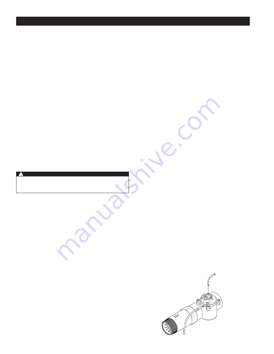
16.  Connect meter cable(s) into meter dome(s) according to Figure 

1. NXT2 & SXT controller meter cable(s) must use side port on 

meter dome(s). Connect the other end of the meter cable(s) 

to the control valve’s P5 port located on the control valve’s 

controller of the control valve the meter is plumbed into. For 

HCTA-200 series systems, connect the meter cable to a single 

control valve controller. See pages 14 & 15 for P5 location.

17.  Connect the 24V transformer power supply wire(s) to the  

P14 port(s) of the control valve controller(s). See pages  

14 & 15 for P14 location.

18.  If applicable, install a metal bonding strap across metal inlet 

and outlet plumbing lines to maintain electrical continuity.

The system is now ready for Start Up.
* See Installation Diagrams pages 11–13 of this manual for  

additional information.

WARNING

!

Operating a system without a drain line flow controller will 

cause all media to flow out of the system through the  

drain line.

Start Up Instructions

  1.  Ensure all inlet and outlet isolation valves and the bypass 

valves are in the closed position and the treated water faucet 

hot and cold side are in the open position.

  2. Open the main water supply valve to the building.
  3. Check for leaks and repair as needed.
  4.  Plug the power cord of the control valve into an electrical  

outlet to energize system. 

  5.  Locate “Manually Initiating a Regeneration” on page 18 of 

this manual and follow the steps to place the system into the 

backwash position. Once the system cycles into the back-

wash position, unplug the control valve from the power outlet 

to keep the system in the backwash position.

  6.  Open the inlet isolation valve slightly until water can be heard 

flowing through the isolation valve and allow the mineral tank 

to fill with water. Air will come out of the drain line until the 

mineral tank is full of water. Once water flow at the drain line 

is observed, fully open the inlet valve and allow water flow 

to drain for 10 minutes to flush the resin bed of any color. If 

water at the drain shows any discoloration, continue to flush 

the resin bed until water at the drain is clear.

  7.  After resin bed flushing is complete, plug the system back in 

to the power outlet so that it will return to the service position. 

Repeat steps 4, 5, 6 and 7 on the other tank(s) if this is a Series 

HCTA-200 Duplex Alternating or HCP-200 Progressive system.

  8.  For HCP-200 or HCTA-200 series systems, connect the  

factory supplied inner-connecting communication cable(s) 

between the P1 and P3 ports of the control valve’s controllers 

shown on pages 14 & 15.

  9.  Program the system according to the System Type (see page 20) 

following the Control Valve Programming section beginning  

on page 21.

10.  Put the appropriate amount of water in the brine tank(s). This 

is accomplished by manually cycling the control valve(s) to 

cycle step 4 “Brine Tank Refill” and allowing a complete brine 

tank refill cycle to conclude. This step must be done for each 

brine tank in the system only after the proper brine tank refill 

time has been programmed into each controller. 

11.  Put the appropriate amount of salt in each brine tank. Do Not 

fill the salt level past the brine well lid.

12.  Fully open the outlet isolation valve(s). 
13.  Ensure the bypass valve is in the closed position. 
14.  Check for leaks and repair as needed.
15.  Allow water to flow from the hot and cold side treated faucet 

until all air has been purged from the plumbing system. Then 

close both the hot and cold side treated water faucet.

16.  Turn on water heaters.
Start up is now complete and the system is ready for operation.

Figure 1

Mechanical Meter Cable Inserts Into 
Top Center Port of Meter Dome 

Electronic Meter Cable for NXT2 & SXT 
Controllers Inserts Into Side Port of Meter Dome

Summary of Contents for HC-200 Series

Page 1: ...Installation Operation and Maintenance 2 Commercial Water Softeners Series HC 200 HCTA 200 HCP 200 HC 200 Simplex Systems HCTA 200 Duplex Alternating Systems HCP 200 Duplex Triplex and Quadplex Progre...

Page 2: ...ality components Simple programming corrosion resistant mineral tank s and an easy to service design ensures this system will be durable and easy to maintain Thank You The Watts Team Softened water pr...

Page 3: ...r that is microbiologically unsafe or of unknown quality This system will not make microbiologically unsafe water safe Water that is unsafe must be treated separately from this conditioner Operating a...

Page 4: ...exchange water softening is a process where an ion exchange resin is used to effectively exchange calcium and magnesium hardness cations for sodium cations in the water New or freshly regenerated ion...

Page 5: ...neration B System 7 2 Mineral Tanks 1 Meter Immediate Regeneration C System 14 2 8 Mineral Tanks 2 8 Meters Immediate Regeneration Progressive Flow Tank Staging GPM Threshold for Progressive Feature _...

Page 6: ...2184 977 16 2449 361 8 917 361 8 917 39 991 60 1524 1560 709 Series HCTA 200 MODEL NO DIMENSIONS WEIGHTS A B C D E F G in in in mm in mm in mm in mm in mm in mm lbs kgs M4043TA 29NT 673 8 1711 673 8 1...

Page 7: ...EL NO ORDERING CODE DESCRIPTION SPACE REQUIRED WEIGHT D X W X H LBS M4043TI NH 68110194 3 Cubic Foot 2 Progressive Duplex Softener with Flow Meters 38 x 55 x 87 530 M4047TI NH 68110195 4 Cubic Foot 2...

Page 8: ...rding to the diagram below according to your specific series number If any components are missing or damaged contact your Watts representative If they can not be reached contact Watts customer service...

Page 9: ...with the top of the tank Test the tape cap to make sure it can not come off during the media loading process 4d For systems 24 in diameter and larger fill the mineral tank 1 3 full with water to prev...

Page 10: ...P14 port s of the control valve controller s See pages 14 15 for P14 location 18 If applicable install a metal bonding strap across metal inlet and outlet plumbing lines to maintain electrical contin...

Page 11: ...te and local codes Do not construct drain line to elevations that exceed 4 feet above the control valve s drain port 11 The full weight of the piping and valves must be supported by pipe hangers or ot...

Page 12: ...12 Installation Diagrams Series HCTA 200 Duplex Alternating Systems Top View Side View Front View...

Page 13: ...13 Installation Diagrams Series HCP 200 Progressive 2 4 Tank Systems Top View Side View Front View...

Page 14: ...Power Supply 3150 3900 Valves Wire Harness Meter Cable Power Supply Communication Cables Hinge Mount mount per valve model noted 44404 Rev A 44403 Rev A HC 200 HCTA 200 HCP 200 Systems use 2900 2900S...

Page 15: ...15 Wiring Diagram 44403 Rev A Wiring diagrams are reference only All wiring should be done by a certified electrician and meet all electrical codes...

Page 16: ...menu navigation Network two to eight valves via shielded CAT5 cables LED Status Indicator Blue In Service Flashing Blue Regeneration Queued Green Regeneration Flashing Green Standby Red Error conditio...

Page 17: ...17 Controller Display...

Page 18: ...egeneration If regeneration occurs for any reason prior to the delayed regeneration time the manual regeneration request shall be cleared Pressing the Extra Cycle button while in regeneration will cau...

Page 19: ...ote Regeneration Ability to trigger a regeneration via a remote input Regeneration Types Softener Filter Meter Delayed When volume remaining reaches zero and the scheduled regeneration time is reached...

Page 20: ...n the NXT2 circuit board Activates during selected cycle step Activates upon selected start time Range 0 91 minutes Deactivates upon selected end time Range Start Time plus 1 minute Activates when sel...

Page 21: ...amming certain values may not be able to be viewed or set 7 The controller will display local information not system information 8 In the event of a regeneration occurring while displaying mas ter pro...

Page 22: ...e button to advance to the next value Press the Left button to retreat to the previous value 3 Where applicable use the Up and Down buttons to adjust a value as desired 4 After progressing through all...

Page 23: ...splayed When regeneration has been completed the display will return to the main screen Example Real time flow rate reading Example Peak flow since last regeneration Example Gallons at the outlet sinc...

Page 24: ...n buttons to adjust as desired 3 Press the Extra Cycle button to advance to the Month field Press the Up or Down buttons to adjust as desired 4 Press the Extra Cycle button to advance to the Calendar...

Page 25: ...X X X X X X X Off Immediate Delayed Auxiliary 1 2 X X X X X X X X X X Off Alarm Based Cycle Based Time Based Lock Window 1 2 X X X X X X X X X X On Off Meter Type X X X X X X X X Paddle 0 75 1 1 5 2...

Page 26: ...the other end of the hose inside a water permeable bag and locate the bag over the floor drain 14 Insert a garden hose into the bag side of the poly vinyl hose to fill the hose and PVC pipe with wate...

Page 27: ...ON 5 0 GPM F 14 SOFTENER 3 1 68108571 V7103 07 FC BUTTON 7 0 GPM F 16 SOFTENER 3 1 68108574 V7103 10 FC BUTTON 10 0 GPM F 18 SOFTENER 3 1 68108575 V7103 12 FC BUTTON 12 0 GPM F 21 SOFTENER 3 1 6810857...

Page 28: ...3E BRINE TANK ASSY 24X41 BLK W GRID AIR CHECK FOR 1 2 BRINE HOSE 13 1 68102503 G2004B BRINE TANK ASSY 24X50 BLK W GRID AIR CHECK FOR 1 2 BRINE HOSE 13 1 68102512 G2009A BRINE TANK ASSY 30X50 BLK W AIR...

Page 29: ...00 Upper Powerhead 2900 UPPER POWERHEAD ITEM NO QTY PART NUMBER DESCRIPTION 1 1 68104633 K4560410 NT UPPER POWERHEAD F 2900S 24V NXT2 W POWER SUPPLY NO TIMER 2 1 68104575 K4560219 02 COVER FOR 2750 29...

Page 30: ...30 NXT2 Controller Assembly NXT2 CONTROLLER ASSEMBLY ITEM NO QTY PART NUMBER DESCRIPTION 1 1 68104777 K4562115 CONTROLLER ASSEMBLY NXT2 1...

Page 31: ...31 NXT to NXT2 Conversion Kit NXT TO NXT2 CONVERSION KIT ITEM NO QTY PART NUMBER DESCRIPTION 1 1 68104778 K4562121 01 CONTROLLER ASSY CONV KIT NXT TO NXT2 W 24V US POWER SUPPLY 1...

Page 32: ...rts 2900 Lower Powerhead 2900 LOWER POWERHEAD ITEM NO QTY PART NUMBER DESCRIPTION 1 1 68104635 K4560411 NT LOWER POWERHEAD F 2900S 24V NTXT2 NO COVER 2 1 68104574 K4560217 02 COVER FOR 2900 LOWER POWE...

Page 33: ...DOWNFLOW F 2900S UPPER 4 1 68104546 K4560128 SEAL SPACER KIT F 2900S LOWER 5 1 68104732 K4561550 PISTON ASSEMBLY DOWNFLOW HWBP F 2900S LOWER 5 1 68104733 K4561555 PISTON ASSEMBLY DOWNFLOW NHWBP F 2900...

Page 34: ...BRINE FLOW WASHER 25 GPM 5 1 68104118 K4512095 BRINE FLOW WASHER 50 GPM 5 1 68104119 K4512097 BRINE FLOW WASHER 1 0 GPM 6 1 68104079 K4510913 00 INJECTOR NOZZLE 00 VIOLET 6 1 68104080 K4510913 000 INJ...

Page 35: ...00 INJECTOR NOZZLE 00 VIOLET 5 1 68104080 K4510913 000 INJECTOR NOZZLE 000 BROWN 5 1 68104081 K4510913 BL INJECTOR NOZZLE 2 BLUE 5 1 68104082 K4510913 G INJECTOR NOZZLE 4 GREEN 5 1 68104083 K4510913 R...

Page 36: ...1 7CB INJECTOR NOZZLE 7C BLACK 3 1 68104214 K4514802 3Y INJECTOR THROAT 3C YELLOW 3 1 68104215 K4514802 4G INJECTOR THROAT 4C GREEN 3 1 68104216 K4514802 5W INJECTOR THROAT 5C WHITE 3 1 68104217 K4514...

Page 37: ...04109 K4512085 FLOW CONTROL WASHER 1 2 GPM 2 1 68104110 K4512086 FLOW CONTROL WASHER 1 5 GPM 2 1 68104111 K4512087 FLOW CONTROL WASHER 2 0 GPM 2 1 68104112 K4512088 FLOW CONTROL WASHER 2 4 GPM 2 1 681...

Page 38: ...h Electronic Meter 2 INCH STAINLESS STEEL METER ASSY ITEM NO QTY PART NUMBER DESCRIPTION 1 1 68104756 K4561934 10 METER ASSEMBLY COMPLETE 2 STAINLESS STEEL MECH ELEC 2 1 68104199 K4514716 METER DOME P...

Page 39: ...generation Inlet of control plugged due to foreign material broken loose from pipes by recent work done on plumbing system Remove piston and clean control valve Loss of mineral through drain line Air...

Page 40: ...ected system type in Master Programming Push correct valve settings in Master Settings Motor Stall No Changes Detected in the Optical Sensor for 6 Seconds The motor is on but no encoder pulses are det...

Page 41: ...41 Water Softener Flow Diagrams Down Flow Brining 2 Backwash Position 3 Brine Position 4 Slow Rinse Position 5 Rapid Rinse Position 6 Brine Tank Refill Position 1 Service Position...

Page 42: ...42 Water Softener Flow Diagrams Up Flow Brining 2 Brine Position 3 Slow Rinse Position 4 Backwash Position 5 Rapid Rinse Position 6 Brine Tank Fill Position 1 Service Position...

Page 43: ...43 Flow Data and Injector Draw Rates Down Flow...

Page 44: ...ilox Micro Z and neutralizing media are also not covered by this warranty In the event of a covered defect within the warranty period the Company will at its option replace or recondition the product...

Reviews: