Installation Guidelines
• Consult local codes for requirements and restrictions applicable
to the area. FEBCO recommends at least 20 psi (138 kPa) for
system supply pressure.
• Install the valve only in the orientation/flow direction shown. The air
inlet operates in the vertical position. Installation in any other manner
causes the device to malfunction.
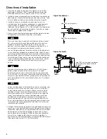
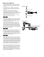
• Install the valve where it is accessible for periodic testing, mainte
nance, and repair. The clearances recommended apply to exterior
and interior installations. (See Figures 1 and 2.) These minimums
do not apply to removable protective enclosures. Refer to local
codes for requirements in the area.
• Before installing the valve into the supply line, flush the line of all
foreign material.
Failure to flush the line may cause the check valves to become
fouled and require disassembly for cleaning. Install the device
where spillage is not objectionable, as instantaneous siphon
conditions and pressure surges can cause spitting.
• When threading the assembly in line, place the wrench only on
the ball valve hex ends. Keep pipe dope (sealant) off the interior
surfaces of the valve. After installation, fill the assembly with water
and test the device to ensure proper operation. Open the inlet ball
valve to pressurize the unit. Slowly open the outlet ball valve to fill
the downstream line.
Maintain the downstream pressure above 5 psi (34 kPa) to keep
the spring-loaded air inlet poppet closed. If the check valve fails to
hold 10 psi minimum, it has become fouled and must be cleaned.
Close both ball valves and bleed pressure from the device before
disassembly. (For more information, see “Service Procedure.”)
All assemblies are tested at the factory for proper operation and
leakage. If the valve does not pass the field test, it may contain
a fouled check valve. This condition is not covered by the fac
tory warranty. Remove the valve cover then inspect and clean
the check seats. Any damage or improper operation caused by
pipeline debris or improper installation/startup is not included in
the factory warranty. In case of a warranty claim, contact the local
supplier or FEBCO representative. Do not remove the assembly
from the pipeline.
• Protect the assembly from freezing and excessive pressure increases.
Pressure increases can be caused by thermal expansion or water
hammer. Eliminate excessive pressure situations to protect the valve
and system from possible damage. Use the plastic test cock plugs
and tethers included in the packaging, if required. For information on
freeze protection, download IS-F-765-Winterization.
Figure 1 Top View
3" Minimum
3" Minimum
FIgure 2 Side View
12" Minimum Above the
Highest Outlet or Water Level
FLOW
2


