


Document #10-32813 Rev A; June 07, 2019
Page
69
of 69
Appendix 3 List of RMA PLUS Figures
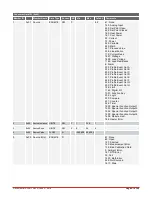
Figure 1: RMA PLUS Configuration Codes for Ordering
Figure 3: Back Plane Dimensions (illustrating 3 connected units)
Figure 4: Ground Wire Connection Point
Figure 5: RMAP-Axxx-xxxx Models
Figure 7: Interconnection Point
Figure 8: Drives Not Mounted to PC, Viewed in Windows Explorer
Figure 9: Use the Eject menu option to mount a drive to the PC
Figure 10: Drives Mounted to PC, Viewed in Windows Explorer
Figure 11: Update Driver Software via Windows Device Manager
Figure 12: Choose "Browse my computer for driver software."
Figure 13: Browse to the MICRO SD drive
Figure 14: Press the Install button
Figure 15: Device Driver Install Success Message
Figure 16: Windows Devices View: All Drives Mounted to the PC
Figure 17: Eject the Drives to Unmount from PC
Figure 18: Dashboard: USB Devices in Tree Node
Figure 19: RMA PLUS Expanded in Tree Node
Figure 20: Dashboard: Drag Device into Data Pane
Figure 21: Dashboard: Ethernet in Data Pane
Figure 22: Dashboard: Edit Static IP Address
Figure 23: Dashboard: Set Ethernet to True
Figure 24: Online Parameters Tab Open
Figure 25: CSV Creator Settings Tab
Figure 26: CSV Creator UI - Mount Drive Buttons
Figure 27: Modbus® TCP and Data Logging Example
Figure 28: Modbus® TCP Address Register
Figure 29: Using Device Addresses
Figure 31: Select Setup from the File Type Menu
Figure 32: Load from RMA PLUS Button
Figure 33: Data Logging Example
Figure 34: RMA PLUS in Windows device manager
Figure 35: Default Diagnostics Web Page
Figure 36: Default HTTPs contents
Figure 37: index.htm token formats


