Watkiss G8 Instruction Manual Download Page 51

3 - Fit the New Parts - Replace the Bender Bar Components

G8 Stitch Head Maintenance Kit Instructions

47

5

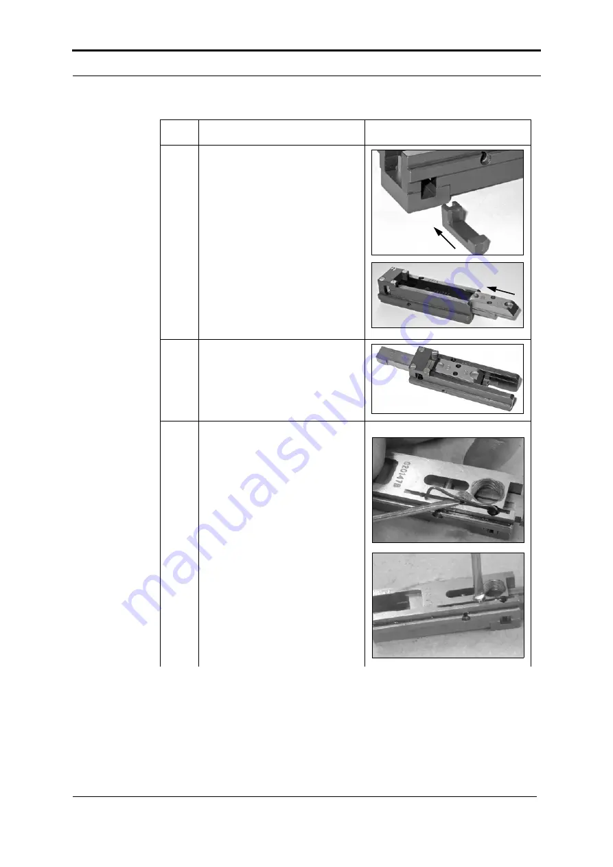
Apply grease to all faces of the 
bender bar latch. 

Apply grease to the inside faces of 
the bender bar where the driver 
bar runs.

Fit the bender bar latch and the 
new driver bar assembly to the 
bender bar.

6

Push the driver bar assembly to 
the end of the bender bar.

7

Fit the bender bar latch spring and 
the bender bar latch spring screw.

See 

FIGURE 3:13.


Step

Action

Information

Summary of Contents for G8

Page 1: ...G8 Stitch Head Maintenance Kit Instruction Manual Issue 2c January 2014 969 344 for kits Nov 13 onwards without the G20199A lower wire tube...

Page 2: ...cument is subject to change without notice Watkiss Automation Limited makes no war ranty of any kind with regard to this material including but not limited to the implied warranties of merchantability...

Page 3: ...the Lower Wire Tube 14 2 5 Remove the Wire holder 16 2 6 Remove the Cutter Box 17 2 7 Remove the Pivot Block Assembly 18 2 8 Remove the Cutter Operating Lever Assembly 19 2 9 Remove the Feed Gear Brac...

Page 4: ...ivot Block and Lubricate and Fit the Wire holder 70 4 10 Fit the Cutter Box and the Middle Wire Tube 74 4 11 Fit the Upper Wire Tube and the Wire Guide Plate 75 4 12 Fit the Stitch Head 81 4 13 Clinch...

Page 5: ...1 000K stitches Additionally the G20199A lower wire tube see A in FIGURE 1 1 that is fitted to stitch heads prior to Lot 14 must also be replaced with the upgraded lower wire tube G20199BAA see B in F...

Page 6: ...Kit 914 881 The G8 Supplementary Stitch Head Maintenance Kit part no 914 881 contains the components that must be inspected and replaced if necessary at 3 000K stitches and 8 000K stitches in addition...

Page 7: ...spring 1 801 613 G20214 Moving cutter screw 1 801 614 G20293 Wire cleaner felt 2 801 620 G20151A Driver bar assembly 1 801 621 G20159 Bender bar friction plug 1 801 622 G20263 Feed lever E clip 2 801...

Page 8: ...1 5 2 2 5 3 4 and 6 mm Screwdrivers small flat blade medium flat blade Pliers needle nose water pump or slip joint Punch 4mm Spanners 7 8 12 13 mm Feeler gauge 0 40mm 952 437 G clamp 100 mm capacity L...

Page 9: ...ith label for the Lot Lot Fitted as Standard to Note 18 Machines from serial number WA PSQ 764 17 Machines from serial number WA PSQ 677 to WA PSQ 763 Later stitch heads can be fitted as needed 16 Mac...

Page 10: ...arlier Lot stitch heads For example it is possible that you can find a Lot 14 stitch head that is modified to Lot 17 specification 1 6 1 Lot 14 Stitch Head Differences The Lot 14 stitch head differenc...

Page 11: ...heads is that Lot 15 heads use the later 801 704 clincher points as standard The 801 704 clincher points are included in the G8 Stitch Head Maintenance Kit part no 914 880 and are retrofittable to al...

Page 12: ...tment and are retrofittable to all stitch heads An update kit 940 154 is available See FIGURE 1 11 and FIGURE 1 12 1 6 5 Lot 18 Stitch Head Differences Reduced tolerance on the pivot block mounting ho...

Page 13: ...sembly and lubrication procedures are the same for all stitch heads 2 1 Remove the Stitch Head from the PSQ Stitch head fixing nut Crank link screw Crank drive link Drive plate Cutter box adjustment b...

Page 14: ...main deck 4 Cut the stitch wire between the wire cleaning felts and the stitch wire cabinet The exact location is not important 5 Mark the position of the stitch head with a pencil or pen This mark is...

Page 15: ...3 Mark the position of the upper wire tube Step Action Information 1 Make a pencil mark on the upper wire tube to show how far the upper wire tube enters into the feed gear bracket Note This step is n...

Page 16: ...3 Remove the Middle Wire Tube 2 Loosen the grub screw See FIGURE 2 2 3 Remove the upper wire tube and the wire guide plate Step Action Information FIGURE 2 4 The middle wire tube Metal spring clip Mi...

Page 17: ...ube See FIGURE 2 4 2 Remove the middle wire tube 3 Identify the type of lower wire tube fitted to the stitch head See FIGURE 2 4 IMPORTANT If the old type of lower wire tube A is fitted then you must...

Page 18: ...ire Tube Button head screw Cutter box fixing screw Cutter box fixing screw Lower wire tube Cutter box shown transparent FIGURE 2 6 Cutter box Grub screws Step Action Information 1 Loosen but do not re...

Page 19: ...ver 4 Clean the inside of the lower wire tube Make sure the wire groove in the rear half of the lower wire tube is free from debris Remove any dust grease or metal particles from inside the lower wire...

Page 20: ...tch Head Maintenance Kit Instructions 2 5 Remove the Wire holder Wire holder Wire holder retaining spring FIGURE 2 7 The wire holder Step Action Information 1 Move the wire holder retaining spring awa...

Page 21: ...IGURE 2 8 The location of the cutter box on the stitch head Metal spring clip Cutter operating slide Cutter box Cutter box fixing screws FIGURE 2 9 Remove the cutter box Cutter operating slide Step Ac...

Page 22: ...thout upgrade Fixing screw M3x6 Fixing screw M3x20 Pivot block assembly FIGURE 2 11 The pivot block assembly From Lot 14 or upgrade fitted Step Action Information 1 Loosen and remove the 2 fixing scre...

Page 23: ...e the Cutter Operating Lever Assembly Tools Screwdriver small flat blade E clip Shown disengaged Cutter operating lever assembly FIGURE 2 12 The cutter operating lever assembly Pivot pin Step Action I...

Page 24: ...ear Bracket Assembly Tools Allen key 2 5mm Fixing screw M3x20 Fixing screw M3x20 Fixing screw M3x6 FIGURE 2 13 The feed gear bracket assembly Feed gear bracket assembly Step Action Information 1 Loose...

Page 25: ...Tools Allen key 6mm FIGURE 2 14 Rear of the G8 stitch head Crank link screw Part No 801 625 Driving slide assembly Retaining screw Lock nut Driving slide Retaining screw FIGURE 2 15 Remove the drivin...

Page 26: ...ck FIGURE 2 16 Remove the feed rack Step Action Information 1 Hold the bonnet in one hand and pull the feed rack with your other hand The feed rack slides from the bon net See FIGURE 2 16 Bonnet Bende...

Page 27: ...engaged Feed lever assembly FIGURE 2 18 Remove the feed lever assembly Feed lever spring Feed lever bushing FIGURE 2 19 Feed lever bushing label Step Action Information 1 Remove the E clip from the pi...

Page 28: ...e nose Screwdriver flat blade Cutter box adjustment stud Cutter box slide plate Dowel pin Cutter adjustment bar Grub screw M5 lock nut FIGURE 2 20 Remove the cutter adjustment bar and slide plate Step...

Page 29: ...ashers in the same order When assembled the disc spring washers must fit face to face Note The later type of cutter box adjustment stud can be fitted to earlier stitch heads See Section 1 6 4 for refe...

Page 30: ...2 Disassemble the Stitch Head Remove the Cutter Adjustment Bar and Slide Plate 26 G8 Stitch Head Maintenance Kit Instructions...

Page 31: ...G8 Stitch Head Maintenance Kit Instructions 27 CHAPTER 3 Fit the New Parts IMPORTANT Unless otherwise documented the disassembly assembly and lubrication procedures are the same for all stitch heads...

Page 32: ...guide plate Wire cleaning felt x 2 Part No 801 614 Washer Spring Nut FIGURE 3 1 Wire cleaning felts assembly Step Action Information 1 Remove the nut spring and washer See FIGURE 3 1 2 Remove and disc...

Page 33: ...100 mm capacity FIGURE 3 2 Rear of the G8 stitch head Crank link screw Part No 801 625 Driving slide assembly Retaining screw Lock nut Step Action Information 1 Loosen but do not remove the lock nut o...

Page 34: ...Fit the lock nut to the new crank link screw 5 Fit the new crank link screw to the driving slide assembly and adjust the depth of the crank link screw Tighten the crank link screw completely Loosen th...

Page 35: ...1058 Do not replace these compo nents as part of stitch head maintenance FIGURE 3 3 Exploded view of the cutter box Cutter operating slide Fixed cutter Spirol pin Cutter operating spring Cutter operat...

Page 36: ...ove and discard the cut ter operating spring See FIGURE 3 4 Step Action Information Factory set 1st service FIGURE 3 5 Rotate the moving cutter Moving cutter Cutter operating slide Mark to show used c...

Page 37: ...the moving cutter to the next available position See FIGURE 3 5 4 Fit and tighten the new moving cutter screw Step Action Information No of Stitches Stitch Head Service Cutter Position 0 Factory Set 1...

Page 38: ...uctions 3 3 3 Assemble the Cutter Box Spirol pin Cutter operating spring Cutter operating slide FIGURE 3 6 Location of the cutter operating spring Fixed cutter Fixed cutter clamp screw Moving cutter C...

Page 39: ...s Allen key 2 5mm Screwdriver flat blade Loctite 222 Kl ber Isoflex NBU 15 grease Step Action Information 1 Loosen but do not remove the fixed cutter clamp screw A that holds the fixed cutter in posit...

Page 40: ...rating slide to the end of the slot Push the fixed cutter from the back until the fixed cutter touches the moving cutter There must be good contact between the fixed and moving cutter See FIGURE 3 8 5...

Page 41: ...slide into the cutter box Tilt the cutter operating slide into the slot in the cutter box Engage the spring and push into position Push the cutter operating slide com pletely into position 10 Test th...

Page 42: ...g Bender bar latch Grub screw for the supporter pivot pin Supporter pivot pin FIGURE 3 9 Components of the bender bar assembly Driver bar assembly Part No 801 620 Driver Part No 801 608 Bender bar Par...

Page 43: ...4 1 Disassemble the Bender Bar Assembly Step Action Information 1 Loosen the grub screw that holds the supporter pivot pin 2 Remove the supporter and the supporter pivot pin See FIGURE 3 9 Tightly hol...

Page 44: ...the supporter pin and fit the new supporter pin from the 914 880 Maintenance Kit See FIGURE 3 10 The supporter pin is a tight fit in the supporter Push the supporter pin from the supporter using a 4mm...

Page 45: ...on plug The bender bar friction bushing is under spring tension See FIGURE 3 9 and FIGURE 3 10 Two versions of the G20161 bender bar friction bushing are used in the G8 stitch head One version has a s...

Page 46: ...e Kit Instructions 5 Remove the bender bar latch spring screw 6 Remove the bender bar latch spring 7 Remove the driver bar assembly and the bender bar latch 8 Remove the driver from the driver bar ass...

Page 47: ...emove and discard the latch housing and the latch housing screws See FIGURE 3 10 From machine PSQ 0300 the latch housing is fastened with Torx screws Torx screws are supplied in the Maintenance Kit an...

Page 48: ...nder bar Part No 801 600 Does not include the latch housing or the latch housing screws FIGURE 3 11 Wear components of the bender bar assembly Bender bar friction plug Part No 801 621 Latch housing Pa...

Page 49: ...ng screw Bender bar latch spring Bender bar latch Grub screw for the supporter pivot pin Supporter pivot pin FIGURE 3 13 Components of the bender bar assembly Step Action Information 1 3000K 8000K onl...

Page 50: ...bar See FIGURE 3 12 Apply grease to the driver bar as shown by the shaded areas in the diagram in particular the cam pro file on the edge of the driver bar 4 Inspect the driver for wear The driver can...

Page 51: ...nder bar latch Apply grease to the inside faces of the bender bar where the driver bar runs Fit the bender bar latch and the new driver bar assembly to the bender bar 6 Push the driver bar assembly to...

Page 52: ...bar friction plug the bender bar friction spring and the bender bar friction bush ing 9 Fit the supporter and the supporter pivot pin 10 Tighten the grub screw to hold the supporter pivot pin in posit...

Page 53: ...rews Clincher plate Clincher slide adjustment block FIGURE 3 14 Clincher assembly components Clincher slide block fixing screws Clincher slide engaged Clincher slide Clincher front plate Clincher back...

Page 54: ...op See FIGURE 3 15 5 Separate the clincher back plate from the clincher front plate See FIGURE 3 15 6 Remove paper dust or debris from the inside of the clincher assembly 7 Remove and discard the clin...

Page 55: ...er slide Clincher points engaged with the clincher slide Clincher slide block clamp Clincher fixing screws Clincher plate Clincher slide adjustment block FIGURE 3 17 Clincher assembly components Clinc...

Page 56: ...Fit the clincher fixing screws 5 Fit the clincher slide block clamp Apply a drop of Loctite 242 to the threads of the clincher slide block clamp fixing screws Fit the clincher slide block clamp Make s...

Page 57: ...Head Maintenance Kit Instructions 53 CHAPTER 4 Lubricate and Assemble the Stitch Head IMPORTANT Unless otherwise documented the disassembly assembly and lubrication pro cedures are the same for all st...

Page 58: ...0mm Kl ber Isoflex NBU 15 grease 1 Lubricate the slot on each side of the bonnet assembly See FIGURE 4 1 4 2 Lubricate and Fit the Bender Bar Assembly Tools Allen key 6mm Feeler gauge 0 40mm Kl ber Is...

Page 59: ...te each side of the bender bar assembly Note Do not lubricate the last 20mm of the bender bar Grease on the last 20mm of the bender bar will transfer to the books 2 Slide the bender bar assembly into...

Page 60: ...0 40mm Kl ber Isoflex NBU 15 grease Driver bar Feed rack Driving slide FIGURE 4 4 Fit the driving slide Driving slide Bonnet 0 40mm feeler gauge 6mm Allen key FIGURE 4 5 Driving slide operational clea...

Page 61: ...slide with the hole in the feed rack 4 Insert but do not tighten the retain ing screw 5 Make sure there is a minimum clearance of 0 40 mm between each side of the driving slide and the bonnet See FIGU...

Page 62: ...Maintenance Kit Instructions 4 5 Lubricate and Fit the Feed Lever Feed lever Pivot pin Feed lever E clip Part No 801 622 FIGURE 4 6 Fit the feed lever Feed lever spring Wire feed cam FIGURE 4 7 Feed...

Page 63: ...le of the tube of grease Wire feed cam Feed lever Step Action Information 1 Lubricate the pivot pin and the feed lever See FIGURE 4 6 2 Lubricate all the surfaces against which the feed lever moves 3...

Page 64: ...lever bushing 5 com plete turns to the right The pitch of the thread is 1mm 5 turns to the right gives a setting of 5mm from the face of the feed lever 9 Fit the 801 650 DO NOT ADJUST label over the...

Page 65: ...r adjustment bar Grub screw M5 lock nut FIGURE 4 10 The cutter adjustment bar and slide plate Step Action Information 1 Lubricate the cutter adjustment bar and the seating slot for the cutter adjustme...

Page 66: ...f the stitch head against which the cutter box slide plate moves 5 Fit the cutter box slide plate 6 Fit the dowel pin and hold in position with the grub screw The top of the dowel pin must be below th...

Page 67: ...ud Lot 16 stitch heads and earlier Step Action Information 1 Fit the washers in the correct order to the cutter box adjustment stud Before Lot 17 Keep the washers in the same order When assembled the...

Page 68: ...ent bar from side to side The cutter adjustment bar must move freely and without tight spots for the complete range of move ment which is approximately 9mm 5 If the cutter adjustment bar does not move...

Page 69: ...design of the cutter box adjustment stud is dif ferent and has plain washers with a compression spring Step Action Information 1 Fit 2 x cutter block adjustment wash ers A to the 801 729 cutter block...

Page 70: ...Operating Lever Tools Kl ber Isoflex NBU 15 grease Pivot pin Cutter operating lever E clip FIGURE 4 11 Fit the cutter operating lever Step Action Information 1 Lubricate the pivot pin and the areas of...

Page 71: ...ly See FIGURE 4 13 Tools Allen keys 2 5mm 3mm Kl ber Isoflex NBU 15 grease Feed gear bracket Fixing screw Friction spring and strip Large feed gear assembly Feed pinion assembly FIGURE 4 12 Feed gear...

Page 72: ...ction strip and spring moved away from the large feed gear assembly Do not tighten completely the fixing screw See FIGURE 4 12 and FIGURE 4 13 2 Remove the large feed gear assem bly Push the feed pini...

Page 73: ...gear assembly See FIGURE 4 12 9 Tighten the fixing screw on the fric tion spring and strip See FIGURE 4 12 10 Fit the complete feed gear bracket assembly to the bonnet Make sure the end of the feed p...

Page 74: ...holder Tools Allen key 2 5mm Screwdriver flat blade Loctite 242 Kl ber Isoflex NBU 15 grease Wire holder retaining spring Bonnet Pivot block FIGURE 4 15 Fit the pivot block Stitch heads up to Lot 13 W...

Page 75: ...upgrade See Section 1 6 1 for refer ence 2 Fit and tighten the fixing screws 3 3000K 8000K Only Inspect the wire holder for wear Look for erosion and loss of defini tion on the contact surfaces 4 If...

Page 76: ...e hook spring screw A See FIGURE 4 17 Fit the 801 651 lock washer to the wire hook spring screw Make a hook from stitch wire Use the stitch wire hook to pull the wire hook spring through the wire hold...

Page 77: ...vot Block and Lubricate and Fit the Wire holder G8 Stitch Head Maintenance Kit Instructions 73 8 Apply grease to the contact patch for the wire holder retaining spring foot 9 Move the wire holder reta...

Page 78: ...iddle Wire Tube Tools Allen key 2 5mm Cutter box Cutter box fixing screws FIGURE 4 19 Fit the cutter box Step Action Information 1 Fit the cutter box to the cutter box slide plate Engage the pin on th...

Page 79: ...upper wire tube and the wire guide plate See FIGURE 4 20 Important For Lot 15 stitch heads and ear lier without the later type of upper wire tube then see Section 4 11 1 For Lot 16 stitch heads and l...

Page 80: ...the Upper Wire Tube Lot 15 and Earlier FIGURE 4 21 Wire feed cam Wire feed off Wire feed on Wire feed cam Feed gears Large feed gear Small feed gear Upper wire tube 2 5mm Allen key FIGURE 4 22 Depth s...

Page 81: ...RE 4 23 3 Insert the upper wire tube into the feed gear bracket until the upper wire tube touches the 2 5mm Allen key See FIGURE 4 20 Note The Allen key gives the correct clearance between the upper w...

Page 82: ...r Wire Tube Lot 16 and Later 5 Use a 3mm Allen key to tighten the grub screw to lock the upper wire tube in position See FIGURE 4 20 6 Remove the Allen keys Step Action Information FIGURE 4 26 Positio...

Page 83: ...The e clip must be in this position to give clearance between the e clip and the bonnet See FIGURE 4 27 2 Attach the upper wire tube to the stitch head See FIGURE 4 20 Insert the upper wire tube in t...

Page 84: ...tions 3 Use a 2mm Allen key to set the clear ance between the upper wire tube and the feed slide See FIGURE 4 28 and FIGURE 4 29 The upper wire tube must not touch the feed slide 4 Use a 3mm Allen key...

Page 85: ...cover Lift the clincher frame assembly Open the gathering area cover Lift the PSQ main deck 2 Put the stitch head in position against the stitcher mounting plate using the pencil mark on the stitcher...

Page 86: ...e to side direction The stitch head must be adjusted to align with the clincher 4 13 1 Remove the Wire holder from the Stitch Head Clincher Stitch head Centre line FIGURE 4 31 Clincher to stitch head...

Page 87: ...k the clincher frame Step Action Information Clincher Alignment marks Driver Bender bar Stitch head FIGURE 4 33 Bender bar and driver at top dead centre Step Action Information 1 Turn on the PSQ 2 Tou...

Page 88: ...ad centre Use the hand crank to operate the stitch head See FIGURE 4 33 6 Compare the centre line of the stitch head with the centre line of the clincher The alignment must be as shown in the diagram...

Page 89: ...al or Chapter 6 of the PSQ User Man ual Stitch head M8 nut Stitcher mounting plate FIGURE 4 34 Stitch head mounting Step Action Information 1 Lift the clincher frame 2 Lift the PSQ main deck 3 Loosen...

Page 90: ...Wire Straightener Endlay alignment jig Stitch wire cabinet Stitch head crank tool Accessory bag FIGURE 4 35 Stitch wire cabinet FIGURE 4 36 Manual operation of the wire feed Large feed gear Small feed...

Page 91: ...Touch MENU Select Service Enter the access code 1973 Touch TEST Touch MOTOR SLOW Touch TOGGLE WIRE FEED Touch MOTOR SLOW 3 Lift the PSQ main deck 4 Get the stitch head crank tool from the storage posi...

Page 92: ...he wire curls up Turn the wire straightener eccentric to the left See FIGURE 4 37 Check the wire straightness and adjust until correct Remove and store the stitch head crank tool Fit the wire holder C...

Page 93: ...nnet Stitch wire in groove FIGURE 4 38 Correct adjustment of the wire holder Correct Incorrect Incorrect FIGURE 4 39 Correct and incorrect position of the wire holder Step Action Information 1 Load a...

Page 94: ...wire See FIGURE 4 39 The piece of stitch wire must align with the grooves in the bender bar If the piece of stitch wire aligns with the grooves in the bender bar then adjustment is not nec essary Go t...

Page 95: ...rub screw See FIGURE 4 40 3 Loosen the lock nut and adjust the position of the eccentric adjuster screw See FIGURE 4 40 4 Tighten the grub screw See FIGURE 4 40 5 Tighten the lock nut and fit the wire...

Page 96: ...92 G8 Stitch Head Maintenance Kit Instructions 4 17 Adjust the Wire Holder Central to the Bender Bar 2 cap head screws Pivot block FIGURE 4 41 The pivot block of the G8 stitch head Locating dowel Loca...

Page 97: ...repeat the cleaning procedure if necessary Step Action Information 1 Loosen but do not remove the 2 cap head screws that hold the pivot block assembly to the main body of the stitch head See FIGURE 4...

Page 98: ...vel the menu also displays counters for the number of gate stitch form and trim cycles You must reset the stitch counter and the stitch cycle counter when the stitch head is serviced To reset the stit...

Page 99: ...e Cutter Box Amended Section 2 7 Remove the Pivot Block Assembly Amended Section 2 14 Remove the Cutter Adjustment Bar and Slide Plate Chapter 3 Amended Section 3 3 Replace the Cutter Box Components A...

Page 100: ...5 List of Changes 96 G8 Stitch Head Maintenance Kit Instructions Appendix A New chapter...

Page 101: ...IRE TUBE G20199B 1 lower wire tube base x1 G20199B 2 lower wire tube cover x1 DW1058 screw M4x6mm button head x1 G20208D wire straightener roller x1 G20206B wire straightener eccentric less adj x1 G20...

Page 102: ...5mm Screwdriver flat blade small Spanners 7mm x 2 Loctite 222 A 1 2 References PSQ Service Manual Issue 4b A 2 Remove the Old Lower Wire Tube Assembly G20199A G20199A lower wire tube Cutter box 2 x gr...

Page 103: ...straightener eccentric Step Action Information 1 Remove the old G20199A lower wire tube See FIGURE A 2 Loosen but do not remove the 2 x grub screws that hold the G20199A lower wire tube in the cutter...

Page 104: ...oller B 4 Remove the G20208B wire straightener roller from the G20206 wire straightener eccentric See FIGURE A 2 Remove and discard the circlip C from the G20206 wire straightener eccentric Remove and...

Page 105: ...G20199BAA Lower Wire Tube Assembly DW1058 button head screw G20199B 2 lower wire tube cover G20199B 1 lower wire tube base FIGURE A 4 The new G20199BAA lower wire tube G20213 wire straightener roll cl...

Page 106: ...ings M4 nuts G20206B wire straightener eccentric FIGURE A 6 Fit the G20206B wire straightener eccentric G20199BAA lower wire tube Cutter box fixing screws Cutter box shown transparent FIGURE A 7 Align...

Page 107: ...0208D wire straightener roller in position 4 Fit the G20206B wire straight ener eccentric to the cutter box See FIGURE A 6 Insert the G20206B wire straight ener eccentric in the hole in the cut ter bo...

Page 108: ...t When you fit the G20199B 2 lower wire tube cover A be careful You must not damage the end of the G20199B 2 lower wire tube cover A 7 Push the assembled G20199BAA lower wire tube to the left The cuto...

Page 109: ...Tube Assembly G8 Stitch Head Maintenance Kit Instructions 105 9 Update the Modification List Label Open the stitch wire cabinet Mark an X over the number 44 on the Modification List Label Close the s...

Page 110: ...APPENDIX A Lower Wire Tube Upgrade Fit the New G20199BAA Lower Wire Tube Assembly 106 G8 Stitch Head Maintenance Kit Instructions...

Page 111: ......

Page 112: ...Watkiss Automation Limited Blaydon Road Middlefield Industrial Estate Sandy Bedfordshire SG19 1RZ United Kingdom Tel 44 0 1767 685700 Fax 44 0 1767 689900 Email info watkiss com Web www watkiss com...

Reviews: