46
47
WL400 UTS & Tap Technical Manual - Issue A, August 2011
STEP 4: RESET PCB SETTING
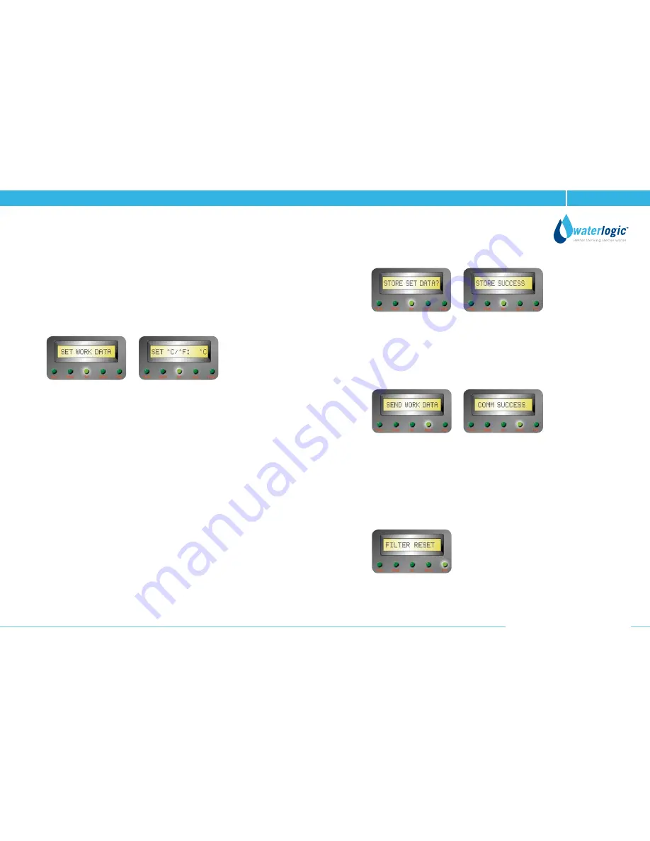
• Press the “Select” button and SET LED will illuminate. The screen will display
SET WORK DATA.
Now press the “Enter” button and the display will change to the first setting
menu SET °C/°F: °C or °F”.
• To change the setting on the display, keep the “Enter” button pressed until
the setting you require appears on the screen.
• To go to the next setting, press the “Down” button, press the “Enter” button
until what you need to set. Repeat this for other setting.
• When all the setting have been correctly set, the final display will show STORE
SET DATA?.
Press the “Enter” button and the screen will diaplay STORING.
The screen will then change to display STORE SUCCESS.
The new setting data is now stored in the Service PCB only and is not within
the WL4 FIREWALL PCB as yet.
• To send the new setting data to the WL4 FIREWALL PCB, press the “ Select”
button, the screen will display SEND WORK DATA and SEND LED will be
illuminated. The Service PCB is now ready to re-program the PCB
in the WL4 FIREWALL. Press the “Send” button on the Service PCB
and the screen will display COMM SUCCESS.
This connfirms the successful transfer of the data.
• THE WL4 FIREWALL PCB is now set to new settings.
STEP 5: FILTER TIMER RESET
• Whenever the filter needs replacing and want to reset, press the “Select”
button and set LED Light at “Filter”.
• When FILTER LED is illuminated and the screen will display will show
FILTER RESET.


