background image

21

INTELLIZONE2 SPECIFICATION CATALOG

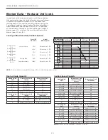
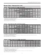
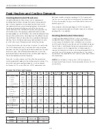
Blower Data - Package Unit cont.

5 Series - Single Speed with Variable Speed ECM

Model

Max ESP

Blower Speed Settings with IntelliZone2 Blower Level Percentages

1

2

3

4

5

6

7

8

9

10

11

12

036

0.50

650

750

850                 

G

1000

1100                 

L   55%

1200          

70%-85%

1300          

H   100%

1400

1500

1550                 

Aux

036 

w/1hp*

0.75

800

1000        

G

1100              

L   55%-70%

1300               

H   85%-100%

1500

1600

1800

1950

2100

2200                

Aux

042

0.50

650

800

900             

G

1050

1150               

L 55%

1250            

70%

1350                  

85%

1450           

H   100%

1550

1600                      

Aux

042 

w/1hp*

0.75

800

900                 

G

1000

1200

L   55%-70%

1400

H  85%-100%

1600

1700

1850

2000

2200                

Aux

2300

2400

048

0.50

650

800

900

1050               

G

1150

1250

1350                       

L   55%

1450                

70%-85%

1550              

H   100%

1600                    

Aux

048 

w/1hp*

0.75

800

900

1000                  

G

1200

1400             

L   55%-70%

1600                  

H   85%-100%

1700

1850

2000

2200              

Aux

2300

2400

060

0.75

800

950

1100               

G

1300

1500                     

L   55%

1750       

70%-85%

1950                            

H   100%

2100

2300

2325                   

Aux

070

0.75

800

950

1100                 

G

1300

1500

1750            

L   55%

1950          

70%-85%

2100                       

H   100%

2300

2325                   

Aux

Blower level percentages are shown with factory recommended blower speed settings
Factory settings are at recommended G-L-H-Aux speed settings

L-H settings MUST be located within boldface CFM range

“Aux” is factory setting for auxiliary heat and must be equal to or above the “H” setting as well as at least the minimum required for the auxiliary heat package
“G” may be located anywhere within the airflow table
CFM is controlled within 5% up to the maximum ESP
Max ESP includes allowance for wet coil and standard filter

6/8/12

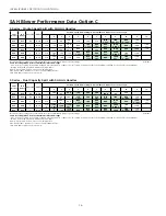
7 Series - Variable Speed with Variable Speed ECM

Model

Max ESP

7 Series Blower Speed Settings with IntelliZone2 Blower Level Percentages

Speed 1

Speed 2

Speed 3

Speed 4

Speed 5

Speed 6

Speed 7 

Speed 8

Speed 9

Speed 10

Speed 11

Speed 12

036 

0.50

285

380              

G

525            

L   25%

675             

40%

815

980                         

55%   

1100                                 
70%

1220

1330                             

85%

1440          

H   100%

1540       

Aux

1575

036 w/1hp*

0.75

480

565                        

G

665                                     

L   25%

761                    

40%

870

1000                        

55%

1100                      
70%

1200

1300                       

85%

1410

H   100%

1520       

Aux

1630

048

0.75

475

620                       

G

730            

L   25%

850                          

40%

1020

1140                        

55%

1270                            

70%

1400

1520                        

85%

1650         

H   100%

1790       

Aux

1925

060

0.75

400

600                       

G

830             

L   25%

1050                         

40%

1230

1400                          

55%

1560                        

70%

1700

1870                         

85%

2010          

H   100%

2140        

Aux

2265

**VS Compressor 

Speed

1-2

3-4

5-6

7-8

9-10

11-12

Blower level percentages are shown with factory recommended blower speed settings
** VS Compressor speed is given for the factory default cfm settings.  When the cfm default settings are changed it will change the relationship to the compressor 
speed that is shown in the table.  In cooling mode compressor speeds 10-12 are only available when SuperBoost mode is selected at the thermostat.
* optional 1 HP ECM
Factory speed settings are at recommended G, L , H and Aux positions
“G” may be located anywhere within the airflow table

“L” setting should be located within the boldface CFM range

“H” setting MUST be located within the shaded CFM range
“Aux” setting MUST be equal to or greater than the minimum allowable CFM for the auxiliary heater kit (see auxiliary heat ratings table)
CFM is controlled within 5% up to the maximum ESP
Max ESP includes allowance for wet coil and standard filter

6/7/12

5 Series - Dual Capacity with Variable Speed ECM

MODEL

MAX ESP

AIR FLOW SPEED SETTINGS

1

2

3

4

5

6

7

8

9

10

11

12

026

0.50

400

G

500

600

L 55%

700

70%

800
85%

900

H 100%

1000

1100

1200

Aux

038

0.50

650

750

G

850

L 55%

1000

1100

1200

1300

H 100%

1400

1500

1550

Aux

038 w/1hp*

0.75

800

G  L 55%

1000

70%

1100

85%

1300

H 100%

1500

1600

1800

1875

1925

2000

Aux

049

0.50

650

800

G

900

1050

L 55%

1150

1250

70%

1350

85%

1450

1550

H 100%

1575

Aux

049 w/1hp*

0.75

800

900

G

1000

L 55%

1200

70%

1400

85%

1600

H 100%

1700

1850

2000

2200

Aux

2300

2400

064

0.75

800

950

G

1100

L 55%

1300

70%

1500

85%

1750

H 100%

1950

2100

2300

2325

Aux

072

0.75

800

950

1100

G

1300

L 55%

1500

70%

1750

85%

1950

H 100%

2100

2300

2325

Aux

10/5/12

Factory settings are at recommended G-L-H-Aux speed settings

L-H settings MUST be located within boldface CFM range

“Aux” is factory setting for auxiliary heat and must be equal to or above the “H” setting as well as at least the minimum required for the auxiliary heat package

“G” may be located anywhere within the airflow table

CFM is controlled within ±5% up to the maximum ESP
Max ESP includes allowance for wet coil and standard filter

Summary of Contents for IntelliZone2 MasterStat

Page 1: ...ation Damper Speci cations System Application and Design SC1578EW 05 17 IntelliZone2 Speci cation Catalog and Design Guide Six Zone Capability Comfort Zoning System res f Operation i cations cation an...

Page 2: ......

Page 3: ...9 16 Description of Operation 17 Blower Data 18 21 Wiring Schematic 22 Damper Specifications 23 Zone Selection 24 25 Special Zoning Applications 26 Peak Heating and Cooling Demands 27 System Sizing 2...

Page 4: ...e of full communication and control of the variable speed compressor bearing 7 Series The IntelliZone2 System is a perfect match to 5 and 7 Series geothermal systems extending comfort and energy savin...

Page 5: ...rol Basement Zone Main Living Area Zone Master Suite Zone Bedrooms Zone The above illustration is representational and is not intended as a guide for IntelliZone2 system installation Zoning is particu...

Page 6: ...ht speeds on line at all times has the ability to deliver the correct amount of airflow that the structure is calling for there is no need for bypass When utilized properly the ECM motor will provide...

Page 7: ...ty and 50 single speed Individual zone selectable economy or comfort modes Four staging options normal quicker faster1 and faster2 to allow a wide range of comfort and energy consumption solutions Sep...

Page 8: ...r any of Zones 2 through 6 It has full setback capability through the MasterStat interface only and communicates to the IntelliZone2 system IntelliZone2 Outdoor Sensor The IntelliZone2 Outdoor Sensor...

Page 9: ...ModBus A small LED is located next to each of the communication ports to aid in evaluating active communication at that specific port This is true for each board The blinking indicates transmission o...

Page 10: ...uipment can have up to the maximum of 6 zones NOTE If the number of zones selected Is less than 6 the remaining zones will be disabled IntelliZone2 Con guration cont ZoneStats SensorStats PCB A R C B...

Page 11: ...g if after another continuous 15 minutes the H3 demand is still present from a 45 or 70 zone third stage will be activated until the zone call is reduced to a H2 Airflow will increase with compressor...

Page 12: ...f the IntelliZone2 is set for quicker upstaging it drops to the total system demand required 41 to initiate a Y2 output By this example it will require a Y2 call from one zone 50 and a Y1 call from th...

Page 13: ...d by the fan demand total zone Normal is the recommended airflow level Selecting Expanded will increase the highest airflow level by one level and decrease the lowest airflow level by one level from N...

Page 14: ...l Fuel operation is terminated all zone dampers will close 6 There will be a 4 minute time delay once Dual Fuel operation is terminated before compressor operation for cooling or heating may begin Fan...

Page 15: ...set to NONE to 12 months in 3 month increments Dealer Information Allows the input of the dealer name phone address e mail and website Simply press the screen segment where you want to enter informat...

Page 16: ...ompressor speeds 10 12 if needed This screen will allow the homeowner to turn the SuperBoost option ON or OFF The SuperBoost option will be enabled by default for a 24 hour period of time then will au...

Page 17: ...2nd stage Y1 Y2 Blower speed will be the H setting of the ECM which is set up at the heat pump control Description of Operation Package Unit Heating Unit 2nd stage Single Dual Capacity Compressor and...

Page 18: ...t mode has been activated The temperature of the structure will be controlled by the zone 1 MasterStat while other zones are ignored When a demand for heat occurs at the MasterStat all zone dampers ar...

Page 19: ...rflow activated by Aux or Emergency heat call selection must be greater than high and allow proper airflow for the installed electric heat heat pump model Airflow Selection Variable Speed Airflow from...

Page 20: ...Capacity Heating Unit Call Blower Level Call Normal Staging Shown Blower Level Call Dehumid H1 or H2 25 or 40 na H3 or H4 25 or 40 or 55 na H5 or H6 40 or 55 or 70 na H7 or H8 55 or 70 or 85 na H9 or...

Page 21: ...60 0 75 400 600 G 830 L 25 1050 40 1230 1400 55 1560 70 1700 1870 85 2010 H 100 2140 Aux 2265 VS Compressor Speed 1 2 3 4 5 6 7 8 9 10 11 12 Blower level percentages are shown with factory recommended...

Page 22: ...ce velocity of the air coil Face Velocity fpm Airflow cfm Face Area sq ft Then for velocities of 200 fpm reduce the static capability by 0 03 in wg 300 fpm by 0 08 in wg 400 fpm by 0 12in wg and 500 f...

Page 23: ...Drive Open Drive Close 3 Wire Damper Zone ID must be set for each Zone 2 6 ID can be confirmed on ZoneStat by pressing cancel button for 5 sec ID shown on display See Zone ID Codes Zone ID must be set...

Page 24: ...d bearing to prevent binding Damper blades which close against a 1 foam seal for air tightness Damper position indicator Available in 5 inch through 18 inch diameters Air leakage less than 6 2 in W G...

Page 25: ...b and office areas The waiting room is an excellent zone because the number of people will vary during the day usually an exterior door is opened frequently and these rooms require large amounts of ai...

Page 26: ...or direct supply air Do not place a thermostat on an outside wall Follow the same guidelines that apply with standard thermostat installation If two or more rooms are on a single zone locate the ther...

Page 27: ...itioned zones may include unfinished areas Both of these represent areas in which reduced setpoints are desired to limit energy use In these zones a continuous blower speed should not be selected Due...

Page 28: ...ntial loads now calculate peak zone loads check your software package for its capability Heating Dominated Structures In heating dominated structures such as northern residential homes where units are...

Page 29: ...pe supplying the entire home is a one inch diameter pipe This pipe supplies all of the lavatories showers tubs kitchen spigots and clothes washer There may be three outdoor spigots and two showers in...

Page 30: ...appliances Up to six zones with variable speed four with dual capacity and two with single speed units All dampers should be located as close to the main trunk as possible to limit the amount of pres...

Page 31: ...31 INTELLIZONE2 SPECIFICATION CATALOG IntelliZone2 with SAH Air Handler...

Page 32: ...the heat pump control Heating Unit 2nd stage Single Dual Capacity Compressor and 5 Speed ECM Operation as stated above with separate zone call levels of YI Y2 and W being translated into unit call 2n...

Page 33: ...he other mode selections at the MasterStat as well as all zone thermostat fault LED s stop flashing indicating emergency heat mode has been deactivated and normal IntelliZone2 operation may resume Con...

Page 34: ...0 1445 1400 1375 1350 1325 1300 1270 1240 1210 1180 1120 1000 930 048 High 5 W 11 x 10 1 1960 1945 1930 1915 1900 1880 1860 1845 1830 1810 1790 1750 1700 1660 1600 Med High 4 Y2 1790 1775 1760 1745 17...

Page 35: ...ressure increases airflow decreases resulting in less torque on the rotor The motor responds only to changes in torque and adjusts its speed accordingly The 5 Speed ECM motor is powered by line voltag...

Page 36: ...olled within 5 up to the maximum ESP Max ESP includes allowance for wet coil and standard filter SAH Air Handler with control option C 3 10 2017 5 Series Dual Capacity Split with SAH Air Handler Split...

Page 37: ...ithout an AID Tool The blower speeds for G Low Y1 High Y2 and Aux can be adjusted directly at the Aurora ABC board which utilizes the push button SW1 on the ABC board This procedure is outlined in the...

Page 38: ...Drive Close Spring Open Drive Open Drive Close 3 Wire Damper Zone ID must be set for each Zone 2 6 ID can be confirmed on ZoneStat by pressing cancel button for 5 sec ID shown on display See Zone ID...

Page 39: ...DQGOHU RDUG LQ 6 3 3RODUL HG FRQQHFWRU DFWRU RZ YROWDJH ZLULQJ LHOG ORZ YROWDJH ZLULQJ HJHQG 3 LUH QXW 6FUHZ 7HUPLQDO 6WULS 3 56 1 7 3 56 3 5 5 XURUD DVH RQWURO LQ RPSUHVVRU 6HFWLRQ 5 3 HDW 3XPS 5 3...

Page 40: ...CC NO ACC NC R C G Y1 EH2 C EH1 C CO C R C R Off Fault LED1 R Status LED3 Config LED2 CC2 CC F C R F FG CC CCG CC2 HI CC2 LO CC2 G REVREV FP1 FP1 FP2 FP2 LPS LPS HPSHPS Aurora Base Control ABC in Comp...

Page 41: ...itch Field wire lug Ground HE PB Heater element Power block Legend N O N C G L1 ER1 to ER4 Aux heat stage relays 1 2 3 P EHC EHC Breaker TS Notes 1 To operate in 208V mode replace the blue transformer...

Page 42: ...42 INTELLIZONE2 SPECIFICATION CATALOG Notes...

Page 43: ...JM Misc Minor Revisions to Configuration section 03 Nov 2015 MA 13 14 Added Dual Fuel Description 07 April 2015 MA All Minor revisions added AWL Information 12 Feb 2015 MA All Software Update 04 June...

Page 44: ...onal Inc 9000 Conservation Way Fort Wayne IN 46809 9794 WaterFurnace has a policy of continual product research and development and reserves the right to change design and speci cations without notice...

Reviews: