


9
INTELLIZONE2 SPECIFICATION CATALOG
IntelliZone2 Confi guration
Aurora System and Communication
Configuration of IntelliZone2
Aurora Communication Basics
The Aurora Control functions around the concept of
modularity and intercommunications between these boards.
The communication is a 4 wire ModBus protocol. ModBus
protocol is an open source protocol becoming more popular
with equipment manufacturers for use in HVAC equipment.
The Aurora has one ‘bus’ for the ABC, AXB, AHB, AWL,
VS Drive, EEV, and thermostats. The AID Tool only plugs
into the ABC AID Tool port, SAH Air Handler AID Tool
port or the AWL (RJ style connector) and will not work
at any other location. The AXB has 3 other independent
ports for differing protocols; for IntelliZone2, ClimateTalk
Components, and Communicating ECM blower motors.
None of these ports comply with the ModBus protocol set
up for the rest of the Aurora system.
The ModBus communication is accomplished within the
cabinet using shielded and ground cabling. This shield is
most important in 7 Series applications where the VS Drive
component, by its very nature, emits electro-magnetic
interference and can interfere with ModBus communications.
Round ferrite ‘donuts’ can be observed at various locations
to aid in cleaning the communication lines. Each line is
comprised of an R (+24VAC), C (common) and a ‘+’ and ‘-‘
communication line. At times the ‘R’ and ‘C’ lines may not be
connected or needed. The terminals marked ‘+’ and ‘-‘ should
not be switched, although damage may not occur to the
boards, communication is not possible. The communication
voltage and current are small therefore 24 awg wire is
adequate for these communication lines and a shield is not
required but recommended in high EMI environments.
An extra ‘expansion’ connector is available for connecting
other devices onto the main ABC ModBus.
A small LED is located next to each of the communication
ports to aid in evaluating active communication at that specific
port. This is true for each board. The blinking indicates
transmission or receiving communication activity.
Configuring the Aurora for the IntelliZone2
'Adding' the IntelliZone2 to the Aurora system can be
accomplished using the AID Tool via the 'Config Aurora'
screen and scrolling to IntelliZone2 selecting and adding.
As always a 'Y' in the communication column shows that
communication is OK. This will initiate communication
between the IntelliZone2 system and the Aurora AXB/ABC.
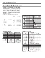
Software Versions
Software versions of the IntelliZone2 MasterStat can be
found in the startup screen or in the AID Tool Aurora
Config screen. Software can be uploaded to the MasterStat
via the USB port on the thermostat. Consult your local
WaterFurnace representative or tech service for details.
Wiring and Configuring the Thermostats/Sensors
The MasterStat and Zone Sensors should be wired using
standard 4-wire thermostat cable (if issues with EMI,
shielded cable should be used and grounded at the ‘–‘
terminal on one end). The other zones should be added
sequentially on the relay board until complete. The dip
switch on the back of each ZoneStat or SensorStat should
be selected for the appropriate zone number; for instance,
Zone 2 stat should be selected using the DIP switch on the
back for ‘off, off, off’.
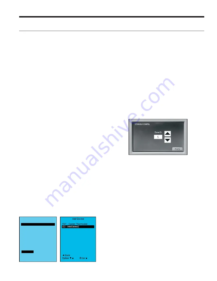
The TPCC32U01 will auto detect that it is attached to the
IntelliZone2 relay panel and will display the screen below.
Use the up/down arrows
▲▼
to select the zone.
If more than one zone is assigned the same zone number
an error will be displayed on the TPCC32U01 and Mas-
terStat. After the initial confi guration to change the zone
numbers enter the confi guration mode by a fi nger over the
Zone number in the upper left hand corner for 5 sec. Select
zone number and use the up/down arrow
▲▼
to adjust.
Config Aurora System
Dev Comm Ver
ABC Y X.XX
AXB Y X.XX
Add Device
Remove Device
Back
Option
Enter


