


Page | 39
Crankshaft itself is forged in one piece. Both main bearings and big end bearings temperatures are
continuously monitored.
Counterweights are fitted on every web. High degree of balancing results in an even and thick oil
film for all bearings.
The connecting rods are arranged side-by-side and the diameters of the crank pins and journals
are equal irrespective of the cylinder number.
All crankshafts can be provided with torsional vibration dampers or tuning masses at the free end
of the engine, if necessary. Main features of crankshaft design: clean steel technology minimizes
the amount of slag forming elements and guarantees superior material durability.
The crankshaft alignment is always done on a thoroughly warm engine after the engine is stopped.
4.2.3
Connecting rod
The connecting rod is of forged alloy steel. All connecting rod studs are hydraulically tightened.
The connecting rod is of a three-piece design, which gives a minimum dismantling height and
enables the piston to be dismounted without opening the big end bearing.
4.2.4
Main bearings and big end bearings
The main bearings and the big end bearings are of tri-metal design with steel back, lead-bronze
lining and a soft running layer. The bearings are covered with a Sn-flash for corrosion protection.
Even minor form deviations can become visible on the bearing surface in the running in phase. This
has no negative influence on the bearing function. A wireless system for real-time temperature
monitoring of connecting rod big end bearings, "BEB monitoring system", is as standard.
4.2.5
Cylinder liner
The cylinder liners are centrifugally cast of a special alloyed cast iron. The top collar of the cylinder
liner is provided with a water jacket for distributing cooling water through the cylinder liner cooling
bores. This will give an efficient control of the liner temperature. An oil lubrication system inside the
cylinder liner lubricates the gudgeon pin bearing and also cools piston crown through the oil
channels underside of the piston.
4.2.6
Piston
The piston is of composite type with steel crown and nodular cast iron skirt. A piston skirt lubricating
system, featuring oil bores in a groove on the piston skirt, lubricates the piston skirt/cylinder liner.
The piston top is oil cooled by the same system mentioned above. The piston ring grooves are
hardened for extended lifetime.
4.2.7
Piston rings
The piston ring set are located in the piston crown and consists of two directional compression rings
and one spring-loaded conformable oil scraper ring. Running face of compression rings are
chromium-ceramic-plated.
4.2.8
Cylinder head
The cross-flow cylinder head is made of cast iron. The mechanical load is absorbed by a flame
plate, which together with the upper deck and the side walls form a rigid box section. There are four
hydraulically tightened cylinder head bolts. The exhaust valve seats and the flame deck are
efficiently and direct water-cooled. The valve seat rings are made of alloyed steel, for wear
Summary of Contents for 31SG
Page 1: ...Page 1 PRODUCT GUIDE W rtsil 31SG...
Page 4: ...Page 4 This page intentionally left blank...
Page 8: ...Page 8 This page intentionally left blank...
Page 14: ...Page 14 This page intentionally left blank...
Page 21: ...Page 21 This page intentionally left blank...
Page 43: ...Page 43 This page intentionally left blank...
Page 49: ...Page 49 Fig 5 1 Flexible hoses...
Page 52: ...Page 52 This page intentionally left blank...
Page 58: ...Page 58 Fig 6 4 Gas valve unit reference P I diagram DAAF051037D...
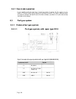
Page 60: ...Page 60 Fig 6 7 Gas valve unit P I diagram open type DAAF085795A...
Page 64: ...Page 64 Fig 7 2 Lubricating oil system single engine wet sump DAAF301501B...
Page 65: ...Page 65 Fig 7 3 Lubricating oil system Gas multiple engines wet sump DAAF301500A...
Page 72: ...Page 72 This page intentionally left blank...
Page 77: ...Page 77 Fig 9 1 Example diagram for multiple main engines DAAF301505A...
Page 87: ...Page 87 This page intentionally left blank...
Page 98: ...Page 98...
Page 109: ...Page 109 This page intentionally left blank...
Page 113: ...Page 113 This page intentionally left blank...
Page 119: ...Page 119 This page intentionally left blank...
Page 122: ...Page 122 18 4 1 Service space requirement 18 4 1 1 Service space requirement engine...
Page 124: ...Page 124 This page intentionally left blank...
Page 127: ...Page 127 This page intentionally left blank...
Page 129: ...Page 129 This page intentionally left blank...
Page 132: ...W rtsil 31SG Product Guide Page 132 21 2 Collection of drawing symbols used in drawings...


