


Page | 41
4.2.12 Fuel equipment
When operating the engine, the gas is injected through gas admission valves into the inlet channel
of each cylinder. The gas is mixed with the combustion air immediately upstream of the inlet valve
in the cylinder head and the gas/air mixture will flow into the cylinder during the intake stroke. Since
the gas valve is timed independently of the inlet valve, scavenging of the cylinder is possible without
risk that unburned gas is escaping directly from the inlet to the exhaust. The compressed gas/air
mixture is ignited with a spark plug in the pre-combustion chamber located in the cylinder head is
hydro-mechanically controlled.
4.2.13 Lubricating oil system
The engine internal lubricating oil system include the engine driven lubricating oil pump, the
electrically driven prelubricating oil pump, thermostatic valve, filters and lubricating oil cooler. The
lubricating oil pumps are located in the free end of the engine, while the automatic filter, cooler and
thermostatic valve are integrated into one module.
4.2.14 Cooling water system
The fresh water cooling system is divided into a high temperature (HT) and a low temperature (LT)
circuit.
For engines operating in normal conditions the HT-water is cooling the cylinders (jacket) and the
first stage of the low pressure 2-stage charge air cooler. The LT-water is cooling the lubricating oil
cooler, the second stage of the low pressure 2-stage charge air cooler and the high pressure 1-
stage charge air cooler.
For engines operating in cold conditions the HT-water is cooling the cylinders (Jacket). A HT-water
pump is circulating the cooling water in the circuit and a thermostatic valve mounted in the internal
cooling water system, controls the outlet temperature of the circuit. The LT-circuit is cooling the
Lubricating Oil Cooler (LOC), the second stage of the Low Pressure 2-stage charge air cooler, the
High Pressure 1-stage charge air cooler and the first stage of the low pressure 2-stage charge air
cooler. An LT-thermostatic valve mounted in the external cooling water system, controls the inlet
temperature to the engine for achieving correct receiver temperature.
4.2.15 Exhaust pipes
The exhaust manifold pipes are made of special heat resistant nodular cast iron alloy. The complete
exhaust gas system is enclosed in an insulating box consisting of easily removable panels. Mineral
wool is used as insulating material.
4.2.16 Automation system
The Wärtsilä 31 engine is equipped with an UNIC electronic control system. UNIC have hardwired
interface for control functions and a bus communication interface for alarm and monitoring.
Additionally UNIC includes fuel injection control for engines with electronic fuel injection rate
optimized nozzles.
For more information, see chapter Automation system.
Summary of Contents for 31SG
Page 1: ...Page 1 PRODUCT GUIDE W rtsil 31SG...
Page 4: ...Page 4 This page intentionally left blank...
Page 8: ...Page 8 This page intentionally left blank...
Page 14: ...Page 14 This page intentionally left blank...
Page 21: ...Page 21 This page intentionally left blank...
Page 43: ...Page 43 This page intentionally left blank...
Page 49: ...Page 49 Fig 5 1 Flexible hoses...
Page 52: ...Page 52 This page intentionally left blank...
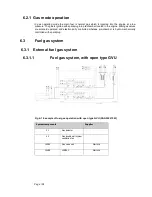
Page 58: ...Page 58 Fig 6 4 Gas valve unit reference P I diagram DAAF051037D...
Page 60: ...Page 60 Fig 6 7 Gas valve unit P I diagram open type DAAF085795A...
Page 64: ...Page 64 Fig 7 2 Lubricating oil system single engine wet sump DAAF301501B...
Page 65: ...Page 65 Fig 7 3 Lubricating oil system Gas multiple engines wet sump DAAF301500A...
Page 72: ...Page 72 This page intentionally left blank...
Page 77: ...Page 77 Fig 9 1 Example diagram for multiple main engines DAAF301505A...
Page 87: ...Page 87 This page intentionally left blank...
Page 98: ...Page 98...
Page 109: ...Page 109 This page intentionally left blank...
Page 113: ...Page 113 This page intentionally left blank...
Page 119: ...Page 119 This page intentionally left blank...
Page 122: ...Page 122 18 4 1 Service space requirement 18 4 1 1 Service space requirement engine...
Page 124: ...Page 124 This page intentionally left blank...
Page 127: ...Page 127 This page intentionally left blank...
Page 129: ...Page 129 This page intentionally left blank...
Page 132: ...W rtsil 31SG Product Guide Page 132 21 2 Collection of drawing symbols used in drawings...