


Page | 34
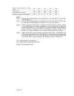
Pressure at engine during start, min. (alarm)
(20°C)
kPa
1500
1500
1500
1500
Pressure, max.
kPa
3000
3000
3000
3000
Low pressure limit in air vessels
kPa
1500
1500
1500
1500
Starting air consumption, start (successful)
Nm
3
6.8
6.8
6.8
6.8
Notes:
Note 1 At ISO 15550 conditions (ambient air temperature 25°C, LT-water 25°C) and 100% load.
Flow tolerance 9%.
Note 2 At ISO 15550 conditions (ambient air temperature 25°C, LT-water 25°C) and 100% load.
Flow tolerance 9% and temperature tolerance 10°C in gas mode operation.
Note 3 At 100% output and nominal speed. The figures are valid for ambient conditions according
to ISO 15550 except for LT-water temperature, which is corresponding to charge air
receiver temperature 55ºC in gas operation with engine driven water and lubricating oil
pumps. Tolerance for cooling water heat 10%, tolerance for radiation heat 20%. Fouling
factors and a margin to be taken into account when dimensioning heat exchangers.
Note 4 Validity of the data in gas fuel operation: total barometric pressure, air temperature and
relative humidity according to ISO 15550:2002(E), LT water temperature corresponding
to receiver temperature 55°C. Lower calorific value 49 700 kJ/kg for gas fuel. With engine
driven pumps (two cooling water pumps, one lubricating oil pump). Tolerance 5%.
AE = Auxiliary engine driving generator
DE = Diesel-Electric engine driving generator
Subject to revision without notice.
Summary of Contents for 31SG
Page 1: ...Page 1 PRODUCT GUIDE W rtsil 31SG...
Page 4: ...Page 4 This page intentionally left blank...
Page 8: ...Page 8 This page intentionally left blank...
Page 14: ...Page 14 This page intentionally left blank...
Page 21: ...Page 21 This page intentionally left blank...
Page 43: ...Page 43 This page intentionally left blank...
Page 49: ...Page 49 Fig 5 1 Flexible hoses...
Page 52: ...Page 52 This page intentionally left blank...
Page 58: ...Page 58 Fig 6 4 Gas valve unit reference P I diagram DAAF051037D...
Page 60: ...Page 60 Fig 6 7 Gas valve unit P I diagram open type DAAF085795A...
Page 64: ...Page 64 Fig 7 2 Lubricating oil system single engine wet sump DAAF301501B...
Page 65: ...Page 65 Fig 7 3 Lubricating oil system Gas multiple engines wet sump DAAF301500A...
Page 72: ...Page 72 This page intentionally left blank...
Page 77: ...Page 77 Fig 9 1 Example diagram for multiple main engines DAAF301505A...
Page 87: ...Page 87 This page intentionally left blank...
Page 98: ...Page 98...
Page 109: ...Page 109 This page intentionally left blank...
Page 113: ...Page 113 This page intentionally left blank...
Page 119: ...Page 119 This page intentionally left blank...
Page 122: ...Page 122 18 4 1 Service space requirement 18 4 1 1 Service space requirement engine...
Page 124: ...Page 124 This page intentionally left blank...
Page 127: ...Page 127 This page intentionally left blank...
Page 129: ...Page 129 This page intentionally left blank...
Page 132: ...W rtsil 31SG Product Guide Page 132 21 2 Collection of drawing symbols used in drawings...


