


Page | 102
14.1.4 Engine safety system
The engine safety module handles fundamental safety functions independently from engine
controls, for example overspeed protection.
Main features:
●
Redundant design for power supply, speed inputs and stop solenoid control
●
Fault detection on sensors, solenoids and wires
●
Led indication of status and detected faults
●
Digital status outputs
●
Shutdown latching and reset
●
Shutdown pre-warning
●
Shutdown override (configuration depending on application)
14.1.5 Power unit
A power unit is delivered with each engine. The power unit supplies DC power to the automation
system on the engine and provides isolation from other power supply systems onboard. The
cabinet is designed for bulkhead mounting, protection degree IP44, max. ambient temperature
50°C.
The power unit contains redundant power converters, each converter dimensioned for 100%
load. At least one of the two incoming supplies must be connected to a UPS. The power unit
supplies the automation system on the engine with 24 VDC and 110 VDC.
Power supply from ship's system:
●
Supply 1: 230 VAC / abt. 750 W
●
Supply 2: 230 VAC / abt. 750 W
14.1.6 Ethernet communication
Ethernet switch and firewall/router are installed in a steel sheet cabinet for bulkhead mounting,
protection class IP44.
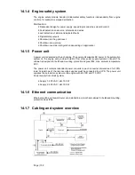
14.1.7 Cabling and system overview
Summary of Contents for 31SG
Page 1: ...Page 1 PRODUCT GUIDE W rtsil 31SG...
Page 4: ...Page 4 This page intentionally left blank...
Page 8: ...Page 8 This page intentionally left blank...
Page 14: ...Page 14 This page intentionally left blank...
Page 21: ...Page 21 This page intentionally left blank...
Page 43: ...Page 43 This page intentionally left blank...
Page 49: ...Page 49 Fig 5 1 Flexible hoses...
Page 52: ...Page 52 This page intentionally left blank...
Page 58: ...Page 58 Fig 6 4 Gas valve unit reference P I diagram DAAF051037D...
Page 60: ...Page 60 Fig 6 7 Gas valve unit P I diagram open type DAAF085795A...
Page 64: ...Page 64 Fig 7 2 Lubricating oil system single engine wet sump DAAF301501B...
Page 65: ...Page 65 Fig 7 3 Lubricating oil system Gas multiple engines wet sump DAAF301500A...
Page 72: ...Page 72 This page intentionally left blank...
Page 77: ...Page 77 Fig 9 1 Example diagram for multiple main engines DAAF301505A...
Page 87: ...Page 87 This page intentionally left blank...
Page 98: ...Page 98...
Page 109: ...Page 109 This page intentionally left blank...
Page 113: ...Page 113 This page intentionally left blank...
Page 119: ...Page 119 This page intentionally left blank...
Page 122: ...Page 122 18 4 1 Service space requirement 18 4 1 1 Service space requirement engine...
Page 124: ...Page 124 This page intentionally left blank...
Page 127: ...Page 127 This page intentionally left blank...
Page 129: ...Page 129 This page intentionally left blank...
Page 132: ...W rtsil 31SG Product Guide Page 132 21 2 Collection of drawing symbols used in drawings...