


Page | 93
11.2.6 Back pressure
The maximum permissible exhaust gas back pressure is stated in chapter Technical Data. The
back pressure in the system must be calculated by the shipyard based on the actual piping
design and the resistance of the components in the exhaust system. The exhaust gas mass flow
and temperature given in chapter Technical Data may be used for the calculation.
Each exhaust pipe should be provided with a connection for measurement of the back pressure.
The back pressure must be measured by the shipyard during the sea trial.
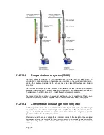
11.2.7 Exhaust gas bellows (5H01, 5H03)
Bellows must be used in the exhaust gas piping where thermal expansion or ship’s structural
deflections have to be segregated. The flexible bellows mounted directly on the turbocharger
outlet serves to minimise the external forces on the turbocharger and thus prevent excessive
vibrations and possible damage. All exhaust gas bellows must be of an approved type.
11.2.8 SCR-unit (11N14)
In gas engines the SCR system is not required, as IMO Tier 3 is already met in. If further
reduction of emissions below IMO Tier 3 is required then an SCR is an option to be used. Please
contact Wärtsilä in these cases.
When a need to install an SCR-unit, the solution requires special arrangement on the engine in
order to keep the exhaust gas temperature and backpressure into SCR-unit working range. The
exhaust gas piping must be straight at least 3...5 meters in front of the SCR unit. If both an
exhaust gas boiler and a SCR unit will be installed, then the exhaust gas boiler shall be installed
after the SCR. Arrangements must be made to ensure that water cannot spill down into the
SCR, when the exhaust boiler is cleaned with water.
More information about the SCR-unit can be found in the Wärtsilä Environmental Product Guide.
11.2.9 Exhaust gas boiler
If exhaust gas boilers are installed, each engine should have a separate exhaust gas boiler.
Alternatively, a common boiler with separate gas sections for each engine is acceptable.
For dimensioning the boiler, the exhaust gas quantities and temperatures given in chapter
Technical data may be used.
11.2.10 Exhaust gas silencers
The exhaust gas silencing can be accomplished either by the patented Compact Silencer
System (CSS) technology or by the conventional exhaust gas silencer.
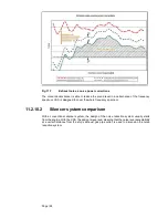
11.2.10.1 Exhaust noise
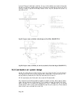
The unattenuated exhaust noise is typically measured in the exhaust duct. The in-duct
measurement is transformed into free field sound power through a number of correction factors.
The spectrum of the required attenuation in the exhaust system is achieved when the free field
sound power (A) is transferred into sound pressure (B) at a certain point and compared with the
allowable sound pressure level (C).
Summary of Contents for 31SG
Page 1: ...Page 1 PRODUCT GUIDE W rtsil 31SG...
Page 4: ...Page 4 This page intentionally left blank...
Page 8: ...Page 8 This page intentionally left blank...
Page 14: ...Page 14 This page intentionally left blank...
Page 21: ...Page 21 This page intentionally left blank...
Page 43: ...Page 43 This page intentionally left blank...
Page 49: ...Page 49 Fig 5 1 Flexible hoses...
Page 52: ...Page 52 This page intentionally left blank...
Page 58: ...Page 58 Fig 6 4 Gas valve unit reference P I diagram DAAF051037D...
Page 60: ...Page 60 Fig 6 7 Gas valve unit P I diagram open type DAAF085795A...
Page 64: ...Page 64 Fig 7 2 Lubricating oil system single engine wet sump DAAF301501B...
Page 65: ...Page 65 Fig 7 3 Lubricating oil system Gas multiple engines wet sump DAAF301500A...
Page 72: ...Page 72 This page intentionally left blank...
Page 77: ...Page 77 Fig 9 1 Example diagram for multiple main engines DAAF301505A...
Page 87: ...Page 87 This page intentionally left blank...
Page 98: ...Page 98...
Page 109: ...Page 109 This page intentionally left blank...
Page 113: ...Page 113 This page intentionally left blank...
Page 119: ...Page 119 This page intentionally left blank...
Page 122: ...Page 122 18 4 1 Service space requirement 18 4 1 1 Service space requirement engine...
Page 124: ...Page 124 This page intentionally left blank...
Page 127: ...Page 127 This page intentionally left blank...
Page 129: ...Page 129 This page intentionally left blank...
Page 132: ...W rtsil 31SG Product Guide Page 132 21 2 Collection of drawing symbols used in drawings...


