Warmington SI 1100 Twin Installation Instructions Manual Download Page 2

11 November 2020


Due to continued product improvement, Warmington Ind LTD reserves the right to change product specifications without prior notification.


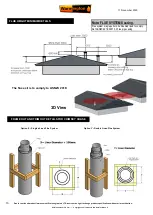
All Dimension are in mm

……. 

Copyright on all products and Specifications © 


2


Prior to Construction and Installation


Important Notes

:


Install to AS/NZS 2918:2001.


Install to manufacture

s specifications.


All new installations require a permit.


For special requirements concerning materials (timber mantle and surrounds) within close proximity of Warmington products, please con-

tact your local Warmington Technical Consultant.
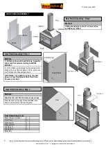
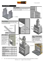


Stage 1:


Frame Construction Procedure by Builder.


Mark out flue centre.


Mark out heat cell clearance requirements.


Construct plinth only, to required height. *


Stage 2:


Install Procedure by Certified 

Warmington Installer

” 

only.


Fit fire to plinth.


Fit adaptor to Firebox.


Fit flue system.


Fit cowl and flashing system


Stage 3:


Finishing Procedure by Builder.


Construct hearth to required thickness.


* Note: Certified installer can install hearth and plinth.


Ensure that the Warmington and flue system is swept annually or more frequently if required.


To sweep flue and firebox:


Cover front of fire with sheets.


Remove cowl from top of chimney.


Sweep from the top, down the flue.


Remove all soot and ash.


Ensure cowl and bird protection is clean and replaced.


     Visually inspect fireplace and flue system.


INSTALLATION ORDER OF OPERATIONS


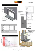
POINTS TO CONSIDER PRIOR TO INSTALLATION


L

ocation of the Fire. Open fires are better located at one end of a room or area, as they project the heat away from their opening.


The Topography of the land .


         The slope and position of the land in relation to the home has a bearing on how the wind will interact with the fire and flue system. Care 

needs to be taken to ensure that the flue termination is in the correct position to maximise performance.


The Prevailing Wind.


         Care needs to be taken to ensure that the flue termination is in the correct position as wind and gusts that hits the flue and cowl system may 

overcome the cowl and draft back down the flue into the home. This can be a combination of down draft and high pressure.
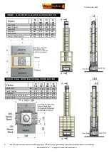


Hearth and Plinth:


         The Height of the Hearth off the Floor. The Finishing that is to be used on the Hearth is to be allowed for at the design stage.


          Note : Ensure Air Intake at Base of Firebox is not blocked or restricted .


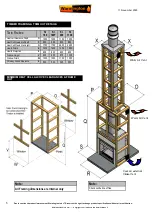
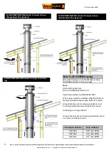
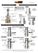
Positioning of the Flue System:


         There is a maximum distance that an offset flue can be Installed . Reference to AS/NZS 2918:2001 . 


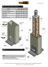
Flue And Fire Clearance:


          To be maintained to the Manufactures Instructions &/or Comply with appropriate Standards & Building Codes .


Pressure Differential, Venting & External Air into the Building 

:


         All fires need air to burn and draw correctly, Kitchen Fans, Air Conditioning units, High Wind Zones, Naturally forming Draft spaces, can all 

have an effect on the pressure difference from inside the building to the outside. A lower pressure in the building may induce a draft down 

the flue system and back into the building causing the fire to smoke or spill into the building. 

Care needs to be taken at the design and 

installation stage to adequately vent the building, or some mechanical system to ensure that there is always a neutral or positive 

pressure at the fireplace and a negative pressure at the flue outlet. 

This will ensure that the draft in the flue system is always to the 

outside.


CAITEC AIR

” 

the limits and requirements. See details in these Spec

s


Wind Noise:


        You may encounter wind noise in some installations. It is recommended


 to use an enclosed chase with a chimney pot to help reduce noise. 

There will always be some noise from the flue systems of all fireplaces.


Summary of Contents for SI 1100 Twin

Page 1: ...mington Fire Installation The Warmington unit is to be Installed by a Certified Warmington Installer or an Approved NZHHA Installation Technician See www homeheat co nz members for a Certified NZHHA S...

Page 2: ...tem Care needs to be taken to ensure that the flue termination is in the correct position to maximise performance The Prevailing Wind Care needs to be taken to ensure that the flue termination is in t...

Page 3: ...350 350 425 450 Flue K 300 300 325 350 Flue Liner L 400 400 425 450 Fascia Width M 1040 1040 1160 1360 Fascia Height N 840 925 995 1045 Heat Output kW Peak 24 26 32 35 Range 15 17 17 19 18 21 19 22 E...

Page 4: ...hielding around the fire system This is a general installation guide only Contact a NZHHA Installer for Installation Advice or go to www homeheat co nz then select Members select your Region Installer...

Page 5: ...000 1100 1350 Heat Cell Clearance Depth P 680 680 830 880 Heat Cell Clearance Height Q 1700 1700 2400 2400 Hearth Width R 1200 1200 1350 1550 Hearth Projection S 600 600 600 600 Window Height V 825 90...

Page 6: ...1550 Hearth Projection S 600 600 600 600 Plinth Width T 1000 1000 1100 1350 Plinth Depth U 680 680 830 880 Centre of Flue J 350 350 425 450 Chimney Chase Clearance X 500 500 525 550 TIMBER PLAN FRONT...

Page 7: ...Width OO 1000 1000 1210 1210 Heat Cell Clearance Depth blockwork PP 680 680 830 880 Heat Cell Clearance Height QQ 1700 1700 2400 2400 Hearth Width RR 1200 1200 1350 1550 Hearth Projection SS 600 600...

Page 8: ...ix down Assemble adaptor and flue system according to AS NZS 2918 2001 2 Fix front panel on by insuring the location tag is posi tioned at the top of the side panels Clamp secure and rivet front panel...

Page 9: ...C Method Assemble together fascia side panels and top panel us ing fastenings pro vided Slide fascia down the front flange into position no less than 15mm overlap on each side Note 4 Fixing Fascia to...

Page 10: ...with ASNZS 2918 2001 4 9 1 1 NOTE The last length of flue pipe needs to extend past the liner so that when the top spider and the Flashing cone are fitted that the flashing cone and the flue pipe are...

Page 11: ...en flashing Butynol Dectite an Additional Flue pipe Baffle is required All external air vents ceiling penetrations must be bird proofed with permanently fixed screens All flashing to comply with E2 Te...

Page 12: ...and Specifications 12 SETTING ADD COWL AND FLASHING CONE HEIGHT CHIMNEY CHASE FLASHING AND AIR VENTILATION OPTIONS VENTING THROUGH CHIMNEY CHASE VENTING THROUGH FLASHING No Insulation under flashing...

Page 13: ...in mm Copyright on all products and Specifications 13 FLUE HEIGHT MINIMUM DETAILS FRAME OUT AND TRIM OUT DETAILS FOR CHIMNEY CHASE Option X Singled Lined Flue System Option Y Double Lined Flue System...

Page 14: ...mension are in mm Copyright on all products and Specifications 14 COMBUSTIBLE MANTLE CLEARANCES HEARTH CLEARANCES Note For Combustible Floors Minimum Hearth of 380mm A must be maintained Mantle Cleara...

Page 15: ...S WARNING ANY MODIFICATION OF THE APPLIANCE THAT HAS NOT BEEN APPROVED IN WRITING BY THE TESTING AUTHORITY IS CONSIDERED AS BREACHING AS NZS 4013 WARNING DO NOT USE FLAMMABLE LIQUIDS OR AEROSOLS TO ST...

Reviews: