13
2.3. HYDRAULIC INSTALLATION RULES
2.3.1. Radiator (Heating) Water Structure
Warning: In order to prevent invalidity of device warranty prior
to making combi connections, clean possible residues found
in main heat exchangers (pipes, heater assembly, etc.) with
dissolvent or equal substances, otherwise they will negatively affect
functioning of the combi. In order to prevent limescale in the radiator
follow rules envisaged by standards regarding domestic hot water and
radiator installations.
Warning: It is recommended to install a Anti-Lime Kit for
preventing occurrence of limescale at places where water
hardness is higher than 25 French degree in order to protect
service life and efficiency of the hot water tap heat exchanger.
2.3.2. Filling/Emptying Radiator Installation
Ensure that the pressure reaches to 1-1,5 bar in the Manometer
indicated with M symbol by rotating the Filling Tap indicated with F
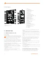
symbol in the Lower View image in Page 6-7 for filling the closed circuit
radiator installation after installation of the combi and close the Filling
Tap by rotating clockwise and re-discharge the air with air relief valves
of the radiator.
Combi safety valve relief should be connected to a discharge cone.
Otherwise, safety valve shall be activated and manufacturer shall not be
responsible due to water discharge around the device.
2.3.3. Circulation Pump
As the combi is equipped with a pump having 3 speed levels, pump
level should be selected according to critical line pressure loss and
required flow rate should be maintained according to this pressure.
2.3.4. Controls for Initial Operation of Combi
In order to prevent void warranty scope, initial startup of the combi
must be performed by the Warmhaus Authorized Service. Below given
initial preparations should be performed prior to authorized service
appointment request:
- Gas opening approval certificate should be taken from the local gas
company for your gas line,
- Combi electricity connection should be made via 2 or 3 Amps fuse.
- Ensure the home has an uninterrupted water and gas supply..
- Ensure that water is supplied to radiator installation and 1,2 - 1,5 bar
pressure is seen in the combi manometer.
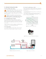
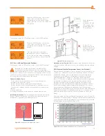
Figure 23
Pump with automatic air relief cock and 3 speed levels.
Figure 22
Pump Flow Rate / Pressure Graphic
Figure 24
Combi general installation scheme
Note:
Connection Group (optional)
Radiator rotation line (cold)
City water line
Condensation
water outlet
Radiator
outlet line
(hot)
Summary of Contents for LAWA
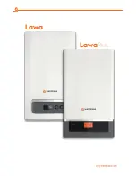
Page 1: ...CONVENTIONAL COMBI BOILERS INSTALLATION USER MANUAL LAWA LAWAPLUS...
Page 2: ...Lawa LawaPlus Enerwa E24 EnerwaPLUSE24...
Page 25: ...25...
Page 26: ...26...
Page 27: ...27...


