background image

29

28

Attention

The material pressure should not exceed 6 bar. The air pressure should not exceed 

6 bar. Otherwise the operational reliability of the spray gun will be impaired.

Warning

It is important to remember to relieve the spray gun of all pressures when work is 

terminated. Lines left under pressure may burst and the released material may injure 

any persons in the vicinity.

5.3 

Spray Pattern Test

Spray pattern tests should be performed whenever:

• 

the spray gun is taken into operation for the first time

• 

the spraying medium has been changed

• 

the spray gun was taken apart for maintenance or repair works.

The spray pattern is best tested using a workpiece sample, a sheet of metal,         

cardboard or paper.

Warning

Keep your hands or other parts of the body away from the spray gun nozzle under 

pressure - risk of injury.

Warning

Make sure that no other people are in the spraying zone when the spray gun is     

started  - risk of injury.

1.  Start the gun to produce a spray pattern sample (see 

5.2 Requirements at the 

Start and Finish of Operation

).

2.  Inspect the sample and, if necessary, adjust the settings of the gun (see 

5.4 

Spray Pattern Adjustment

).

5.4 

Spray Pattern Adjustment

The spray pattern of the Pilot III 2-K can be adjusted as follows:

Adjusting the Material Flow Rate

The material flow rate can be adjusted by turning the adjusting screw (Item 22). The 

material flow is increased by turning it to the left (screwing out), decreased by turning 

it to the right (screwing in).

Adjusting the Material Pressure

The material pressure can only be adjusted at the pump or the pressure tank. Please 

follow the instructions and safety instructions issued by the manufacturer.

5.5 

Retooling the Spray Gun / Repairs

Air cap, material nozzle and needle packing, all chosen for a particular spraying 

material, together form a unit - the nozzle insert assembly. Always change the     

complete insert assembly to maintain the desired spray finish quality.

Warning

Air and material inputs must be shut off prior to retooling - risk of injury.

Note

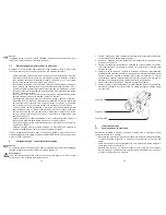
Please refer to the exploded view (page 2) of this manual to perform the steps 

detailed below.

Replacement of Material Nozzle and Air Cap

1.  Unscrew the air cap retaining nut (Item 1).

2.  Remove the air cap (Item 2a / 2b).

3.  Remove the material nozzle (Item 3) from the gun body, using wrench (width 

over flats 12)

4.  Remove the seal (Item 5) from the material nozzle.

Reassembly of the new nozzle insert and the remaining parts is performed in 

reverse order.

Replacement of Material Needle (Component A)

1.  Unscrew the adjusting screw (Item 22).

2.  Remove the spring (Item 21).

3.  Remove the material needle (Item 18) from the gun body.

Reassembly is performed in reverse order. The distance between the tip of the  

material needle for the initial air inlet and the driving sleeve should be 76.5 mm.

Replacement of Material Needle (Component B)

1.  Unscrew the two U-bolts (Item 15) with a screwdriver.

2.  Unscrew the collar nuts (Item 17) (width over flats 9).

3.  Remove the holder for the trigger (Item 16).

4.  Unscrew the material needle (Item 14).

5.  Remove the spring (Item 13) together with thrust washer.

Reassembly is performed in reverse order. 

Summary of Contents for PILOT III 2-K

Page 1: ...g Operating Instructions Instructions de Service Istruzioni per I uso PILOT III 2 K Zweikomponenten Spritzpistole Two Component Spray Gun Pistolet de pulv risation deux composants Pistola a spruzzo pe...

Page 2: ...3 2 Montagewerkzeug f r Einbau PILOT III 2 K Stand Oktober 2008 41 Nadelpackung f r B Komponente 11 12 12 12 13 b 2a 30...

Page 3: ...Seite 6 19 Page 20 33 Page 34 47 Pagina 48 61...

Page 4: ...pritz und Lackiersysteme GmbH K rntner Str 18 30 D 42327 Wuppertal Besondere Hinweise Das Produkt ist zum Einbau in ein anderes Ger t bestimmt Die Inbetriebnahme ist so lange untersagt bis die Konform...

Page 5: ...be 2 V 24 531 13 003 16 B gel f r Abzughebel 1 V 24 531 12 000 17 Bundmutter 1 V 24 531 10 003 18 Materialnadel D sengr e 0 8 1 0 mm 1 V 10 353 06 3 19 Mitnehmer 1 V 10 353 07 000 20 Konterschraube 1...

Page 6: ...pr fen und sicherzustellen dass alle technischen Daten und die Kennzeichnung gem ATEX mit den notwendigen Vorgaben bereinstimmen Bei Anwendungen bei denen der Ausfall des Ger tes zu einer Personengef...

Page 7: ...te Arbeiten mit der Spritzpistole 3 2 Allgemeine Sicherheitshinweise Die einschl gigen Unfallverh tungsvorschriften sowie die sonstigen anerkannten sicherheitstechnischen und arbeitsmedizinischen Rege...

Page 8: ...ln Die Materialmenge wird durch Linksdrehen Ausschrauben erh ht durch Rechtsdrehen Einschrauben verringert Materialdruck regulieren Den Materialdruck k nnen Sie nur an der Pumpe oder am Druckbeh lter...

Page 9: ...nd einen Pinsel Anschlie end wird die Spritzpistole in umgekehrter Reihenfolge zusammengesetzt Undichte Nadelpackung austauschen A Komponente 1 Bauen Sie die Materialnadel gem Materialnadel wechseln A...

Page 10: ...auf gleiche Durchmesser achten Stellschraube etwas Einschrauben Rechtsdrehen Pistole tropft B Komponente Nadelfeder Pos 13 besch digt Materialnadel Pos 14 besch digt O Ring Nadelspitze besch digt aus...

Page 11: ...l Special remarks The named product is intended for installation in other equipment Commissioning is prohibited until such time as the end product has been proved to conform to the provision of the Di...

Page 12: ...31 06 000 15 U Bolt 2 V 24 531 13 003 16 Holder for Trigger 1 V 24 531 12 000 17 Collar Nut 1 V 24 531 10 003 18 Material Needle Nozzle Size 0 8 1 0 mm 1 V 10 353 06 3 19 Driver Pin 1 V 10 353 07 000...

Page 13: ...d the marking of the equipment in accordance with ATEX are compliant with the necessary requirements The operator must provide corresponding safety measures for all applications in which the breakdown...

Page 14: ...raying materials please contact WALTHER Spritz und Lackiersysteme GmbH D 42327 Wuppertal Germany 4 Connection of Input Lines Note Please refer to the exploded view page 2 supplied with this manual whe...

Page 15: ...t screwing in Adjusting the Material Pressure The material pressure can only be adjusted at the pump or the pressure tank Please follow the instructions and safety instructions issued by the manufactu...

Page 16: ...of the cleaning media Aggressive and caustic cleaning agents in particular represent health hazards 6 2 General Cleaning Procedure The spray gun should be frequently cleaned and lubricated to ensure r...

Page 17: ...the following steps 1 Fill the clean material pressure tanks with a cleaning solution compatible with the material used 2 Start the spray gun see 5 2 Requirements at the Start and Finish of Operation...

Page 18: ...n Fabricant WALTHER Spritz und Lackiersysteme GmbH K rntner Str 18 30 D 42327 Wuppertal Tel 49 0 202 787 0 Fax 49 0 202 787 2217 www walther pilot de e mail info walther pilot de D nomination du mod l...

Page 19: ...trier pour le g chette 1 V 24 531 12 000 17 Ecrou chapeau 1 V 24 531 10 003 18 Aiguille mati re p calibres de buse 0 8 1 0 mm 1 V 10 353 06 3 19 Guide d entra nement 1 V 10 353 07 000 20 Contre vis 1...

Page 20: ...s donn es techniques correspondent aux exigences ATEX L exploitant devra prendre les mesures de s curit correspondantes en cas d applications pouvant repr senter un danger pour les personnes Au cas o...

Page 21: ...Spritz und Lackiersysteme GmbH D 42327 Wuppertal 4 Raccordement des conduits d alimentation Recommandation Avant de proc der aux op rations suivantes veuillez consulter le croquis d assemblage situ p...

Page 22: ...re La pression mati re ne peut se r guler qu partir de la pompe ou du r servoir sous pression Respectez les instructions et consignes de s curit du fabricant 5 5 Conversion du pistolet et maintenance...

Page 23: ...travail L application de produits tr s inflammables solvants par exemple multiplie les risques d explosion et d incendie Suivez les consignes d utilisation et de s curit des fabricants de mati res pu...

Page 24: ...l g rement la vis de r glage vers la droite Le pistolet goutte composant B Le ressort Pos 13 est ab m L aiguille Pos 14 sont ab m es Le joint torique est ab m Changez le Changez le Changez le Le jet e...

Page 25: ...o di uso improprio la presente dichiarazione cessa di essere valida Costruttore WALTHER Spritz und Lackiersysteme GmbH K rntner Str 18 30 D 42327 Wuppertal Tel 49 0 202 787 0 Fax 49 0 202 787 2217 www...

Page 26: ...31 13 003 16 Staffa del grilletto 1 V 24 531 12 000 17 Dado a colletto 1 V 24 531 10 003 18 Ago del materiale per diametri di ugello 0 8 1 0 mm 1 V 10 353 06 3 19 Boccola di trascinamento 1 V 10 353 0...

Page 27: ...assicurare che tutti i dati tecnici e la marcatura ATEX corrispondano alle prescrizioni necessarie Nelle applicazioni nelle quali il guasto dell apparecchio pu mettere in pericolo le persone il gestor...

Page 28: ...funzione solo se vengono usate parti originali In caso di domande sull utilizzo privo di rischi della pistola a spruzzo nonch sui materiali utilizzabili con la pistola rivolgersi alla WALTHER Spritz u...

Page 29: ...do le indicazioni Sostituzione dell ago com A 5 2 Mettere in marcia e mettere fuori servitio Prima di attivare la pistola a spruzzo si deve tener conto delle seguenti premesse Stabilire la pressione d...

Page 30: ...p es solventi vi un notevole rischio di esplosione o di incendio Rispettare le norme del fabbricante del detergente I solventi in particolare quelli caustici o corrosivi possono causare infortuni e da...

Page 31: ...verso destra Dalla pistola goc ciola il componente B La molla dell ago danneggiata pos 13 L ago del materiale danneggiato L anello O danneggiato Sostituire Sostituire Sostituire Il getto oscilla o esc...

Page 32: ...on Powder Spray Stands Dryers Ventilation Systems Protective Respiratory Systems and Accessory Items Le Programme de WALTHER PILOT Pistolets de pulv risation manuels Pistolets de pulv risation automat...

Reviews: