


245.805.011
21
Date: 2021-12-09
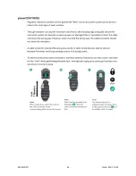
Save changed value
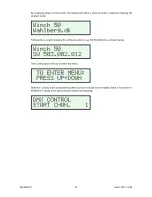
The display shows:
Press
to change the top line to:
Where X is an increasing number from 1 to 20.
Then press and hold
The top line of the display counts up to 20 then shows
OK
.
The value is now saved in the memory.
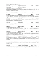
Adjustable parameters
Menu
Description
Range
Default
MAN SPEED
Speed for manual driving
200 1,500
1,500
MAN UP/DWN
Run the motor manual from the menu
MOTOR UP / MOTOR DOWN
DMX ADDRESS
DMX start address
1-506
1
TAC RANGE
Tacho range
1-99,999
10,000
RAMP TIME
Ramping time from 0 to max speed
0.5 10.0
1.0
SPEED MAX
Maximum speed
500 5,000
3,000
SP MIN UP
Minimum speed UP
50 - 1,000
200
SP MIN DWN
Minimum speed DWN
50 - 1,000
200
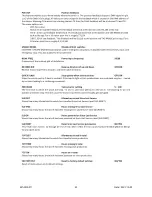
E STOP
Enable/disable emergency stop
OFF/ON
OFF
ADV. MENU
Show advanced menu
OFF/ON
OFF
SLACK DELAY
Delay from slack activation to stop
0 9999
0
POS OUT
Position feedback
OFF/ON
OFF
UNSAFE MODE
Disable all limit switches
OFF/ON
OFF
NOM. FREQ
Power input frequency
50/60
50
REVERSE DIR
Reverse direction of up and down
OFF/ON
OFF
QUICK SLACK
Stop quickly when slack activates
OFF/ON
OFF
PRECISION
Tolerance for settling
5 100
15
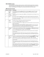
SLS DIST
Kilometers moved Since Last Service
Not adjustable
SLS TIME
Hours moving Since Last Service
Not adjustable
SLS ON
Hours on Since Last Service
Not adjustable
SLS RESET
Reset Since Last Service parameters
NO/YES
NO
TOT DIST
Kilometers moved in total
Not adjustable
TOT TIME
Hours moving in total
Not adjustable
TOT ON
Hours on in total
Not adjustable
FACTORY RST
Reset to factory default settings
NO/YES
NO
MAN SPEED and MAN UP/DWN are used for manual control of the motor.
Summary of Contents for 50 Series
Page 37: ...245 805 011 37 Date 2021 12 09 Winch 50 245...
Page 38: ...245 805 011 38 Date 2021 12 09 Winch 50 Double 246 701...
Page 39: ...245 805 011 39 Date 2021 12 09 Winch 50 Double Power and Cat5 246 704...
Page 40: ...245 805 011 40 Date 2021 12 09...
Page 41: ...245 805 011 41 Date 2021 12 09...
Page 43: ...245 805 011 43 Date 2021 12 09 This page is intentionally left blank...


