background image

ProSpray 24

ProSpray 24

d

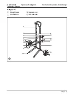
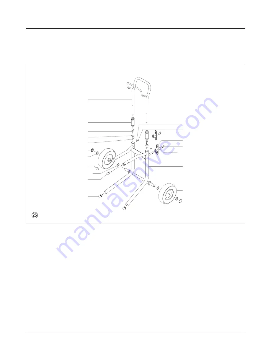
Hoher Wagen

g

Upright cart

f

Chariot haut

i

Carrello alto

1

2

3
4
5

7

11
12

13

11

15

16

14

7

9

10

6

8

Ersatzteilbild

Spare parts diagram

Illustration des pièces de rechange

Figura dei ricambi

Summary of Contents for ProSpray 24

Page 1: ...Operating manual Airless high pressure spraying unit ProSpray 24...

Page 2: ...be used 2 Secure WAGNER spray gun using the safety catch on the trigger 3 Ensure that the unit is properly earthed The connection must take place through a correctly earthed two pole and earth socket...

Page 3: ...ting material or solvents consult a doctor for quick and correct treatment Inform the doctor about the coating material or solvent used Danger Danger Danger Danger P Secure spray gun against unintende...

Page 4: ...ining solvents do not reach the unit and build up there A minimum distance of 5 m between the unit and spray gun is to be maintained P Ventilation when spraying in rooms Adequate ventilation must be g...

Page 5: ...sharp edged additional materials These have a strong wear and tear effect on valves high pressure hose spray gun and tip The durability of these parts cane be reduced appreciably through this 3 Descri...

Page 6: ...8 Relief valve Lever position vertical PRIME k circulation Lever position horizontal SPRAY p 9 ON OFF switch 10 Control system cover 11 Digital Electronic Spray Control ESC system 12 Control panel in...

Page 7: ...iption of unit 1 Pail hook 2 Suction tube 3 Filter 4 Return hose 3 5 Legend for explanatory diagram of upright cart unit 4 1 2 3 3 6 Explanatory diagram of upright cart unit Parts not identified are t...

Page 8: ...m Max sound pressure level 80 dB A Place of measuring 1 m in distance from the unit and 1 6 m above the floor 12 MPa 120 bar operating pressure reverberant floor 3 8 Transportation Pushing or pulling...

Page 9: ...e proper pressure setting for spraying stain lacquer varnish and multi colors If the pressure indicator goes to solid yellow when the pressure is set so that it starts at solid green it indicates one...

Page 10: ...sition SPRAY p spray 7 Trigger the spray gun several times and spray into a collecting container until the coating material exits the spray gun without interruption 8 Increase the pressure by slowly t...

Page 11: ...at startup Also when setting a security code for the first time the Enter Old Code Number screen will not appear i SECURITY CODE SELECT 4 MENU 1 SET MPa 23 0 ACTUAL MPa 22 5 PRESSURE SELECT 4 MENU 1 S...

Page 12: ...chnique Cleaning the unit shutting down 5 Spraying technique Move the spray gun evenly during the spraying process Otherwise the spray pattern will be uneven Carry out the spray movement with the arm...

Page 13: ...s maximum feed quantity constant spraying pressure and problem free functioning of the unit i Danger of short circult through pane trating water Never spray down the unit with high pressure or high pr...

Page 14: ...the SPRAY p spray position Packings sticky or worn Valve balls worn Valve seats worn Upper packing is worn Piston is worn Check voltage supply Turn up pressure control knob Replace Set relief valve t...

Page 15: ...ective Take the sprayer to a Wagner authorized service center for repair Low Voltage Screen E4 The Low Voltage screen appears when the sprayer shuts down because of low input voltage Check the power s...

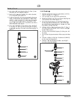
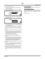
Page 16: ...into alignment 7 Insert the grooved pin 1 to secure the relief valve handle in position 1 7 5 6 4 2 3 Switch the unit OFF Before all repair work Unplug the power plug from the outlet Danger 11 2 Inlet...

Page 17: ...ig 15 Item 1 10 11 12 8 7 11 3 Packings 1 Remove inlet valve housing in accordance with the steps in Chapter 11 2 Page 41 2 It is not necessary to remove the outlet valve 3 Slide the retaining ring 10...

Page 18: ...refully tighten retainer nut 6 with adjusting wrench 20 Position the pump manifold 2 underneath the gear unit housing and push up until it rests against the gear unit housing When the connecting pin h...

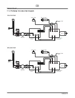
Page 19: ...Board Surge Suppressor Electronic Pressure Control EPC J16 AC Motor AC Neut AC Line AC Motor J9 J2 J1 J12 J7 Switch Ground 100 120 V AC Potentiometer Motor Pressure Sensor Pressure Sensor Jumper Plug...

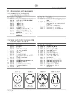
Page 20: ...0 Motor cover 2 0551 440 Screw 4 3 9800 308 Cylinder head screw 4 4 Power cord see below 5 9800 340 Ground screw 6 0551 659 Screw 4 7 0551 720 Pressure control knob 8 0551 721 Digital Electronic Spray...

Page 21: ...ing stand and low boy cart 20 0508 690 Inlet valve housing upright cart unit 21 0508 604 O ring 22 0508 749 Bearing spring 23 0508 601 Filter housing 24 0508 602 Conical spring 25 0508 748 Filter cart...

Page 22: ...ng 9 0508 558 Electronic cover 10 0551 647 Electronic control assembly 230 V AC 0551 731 Electronic control assembly 100 120V AC 11 0551 790 Motor complete 220 240 V AC 50 60 Hz includes items 1 2 10...

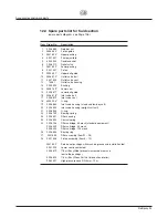
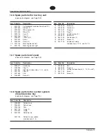
Page 23: ...er No Description 7 0509 856 Nut 8 0507 397 Drip cup 9 0551 818 Left leg includes items 4 5 7 8 10 and 11 10 0551 732 Screw 11 0507 955 Screw 2 12 6 Spare parts list for low boy cart spare parts diagr...

Page 24: ...ability Do not forget the fact that the hard metal insert is brittle Never throw the tip or handle with sharp metal objects The following points must be observed to keep the tip clean and ready for us...

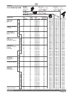
Page 25: ...48 320 0090 719 1088 719 0552 719 819 80 0 019 0 48 400 0090 819 1088 819 0552 819 Mica paints 221 20 0 021 0 53 145 0090 221 1088 221 0552 221 Zinc dust paints 421 40 0 021 0 53 190 0090 421 1088 42...

Page 26: ...Fax 43430528 A B Wagner Spraytech Iberica S A Apartado 132 08750 Molins de Rey Barcelona Spain Phone 93 6800028 Fax 93 6800555 J Wagner France S A R L B P 75 91122 Palaiseau Cedex France Phone 01 601...

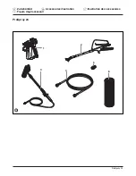
Page 27: ...104 ProSpray 24 d Zubeh rbild g Accessories illustration f Illustration des accessoires i Figura degli accessori 3 1 5 2 4 6 ProSpray 24...

Page 28: ...15 16 17 18 19 20 21 22 Upright Cart Unit ProSpray 24 d Hauptbaugruppe g Main Assembly f Ensemble principal i Gruppo principale Ersatzteilbild Spare parts diagram Illustration des pi ces de rechange F...

Page 29: ...1 12 13 14 15 16 17 18 19 20 2 3 4 5 21 22 24 25 26 23 28 27 ProSpray 24 d Farbstufe g Fluid section f Pompe peinture i Stadio della vernice Ersatzteilbild Spare parts diagram Illustration des pi ces...

Page 30: ...9 11 12 13 14 15 16 17 18 ProSpray 24 d Baugruppe Antrieb g Drive Assembly f Ensemble moteur i Gruppo azionamento Ersatzteilbild Spare parts diagram Illustration des pi ces de rechange Figura dei rica...

Page 31: ...y 24 ProSpray 24 d Hoher Wagen g Upright cart f Chariot haut i Carrello alto 1 2 3 4 5 7 11 12 13 11 15 16 14 7 9 10 6 8 Ersatzteilbild Spare parts diagram Illustration des pi ces de rechange Figura d...

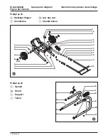
Page 32: ...ces de rechange Figura dei ricambi ProSpray 24 109 ProSpray 24 d Niedriger Wagen g Low boy cart f Chariot bas i Carrello basso 9 10 11 12 13 14 15 16 17 18 20 19 1 2 3 4 6 7 8 3 5 2 4 1 3 5 6 7 11 10...

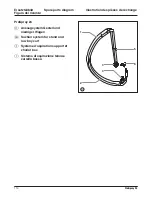
Page 33: ...change Figura dei ricambi 110 ProSpray 24 110 ProSpray 24 1 2 3 4 6 5 ProSpray 24 d Ansaugsystem Gestell und niedriger Wagen g Suction system for stand and low boy cart f Syst me d aspiration support...

Page 34: ...oder uns schriftlich mitzuteilen Wir behalten uns vor die Garantie durch ein Vertragsunternehmen er f llen zu lassen Die Leistung dieser Garantie ist abh ngig vom Nachweis durch Rech nung oder Liefer...

Page 35: ...une restriction des revendications l gales ou contractuelles d finies par nos conditions g n rales de vente J Wagner GmbH Sous r serve de modification Imprim en R F A Avvertenza importante sulla resp...

Page 36: ...eclare that the supplied version of WAGNER ProSpray 24 Complies with the following provisons applying to it 73 23 EEC 89 336 EEC 92 31 EEC 93 68 EEC 98 37 EEC Applied harmonized standards in particula...

Reviews: