background image

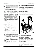
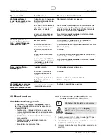
Cariche elettrostatiche (genera-
zione di scintille o di fiamme)

A causa dell'elevata velocità di flusso del ma-

teriale di copertura durante la spruzzatura, in
circostanze particolari sull'apparecchio si
possono accumulare cariche elettrostatiche.
In fase di scarica, queste cariche elettriche

possono causare la formazione di scintille o fiamme. Du-
rante l'installazione elettrica è pertanto necessario colle-
gare correttamente a terra l'apparecchio. La presa di cor-
rente deve essere munita di un contatto di protezione per
la messa a terra in conformità alle norme in materia.

Apparecchio utilizzato in cantieri

Collegamento alla rete elettrica solo tramite un punto
di alimentazione a parte, ad esempio per mezzo di un
interruttore di sicurezza per correnti di guasto con
INF 

30 mA.

Ventilazione nei lavori di spruzza-
tura in ambienti chiusi

Occorre garantire una sufficiente ventilazione per elimi-
nare i vapori di solvente.

Dispositivi di aspirazione

Tali dispositivi vanno installati dal titolare dell'appa-
recchio in conformità alle norme locali.

Messa a terra dell'oggetto da
rivestire

L'oggetto da rivestire deve essere collegato a terra.

Pulizia dell'apparecchio con
solvente

Nella pulizia dell'apparecchio con solvente non

si deve spruzzare o pompare in un recipiente
con una piccola apertura (cocchiume). Pericolo
dovuto alla formazione di una miscela esplosi-
va gas/aria. Il recipiente deve essere collegato
a terra.

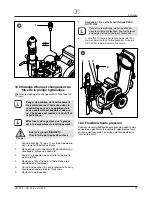
Pulizia dell'apparecchio

Pericolo di cortocircuito dovuto alla pene-
trazione di acqua!

Non pulire mai l'apparecchio con unità a
getto liquido o a getto di vapore ad alta
pressione.

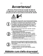
Pericolo

Pericolo

Pericolo

i

HC 35 E • HC 45 E • HC 55 E

93

i

Lavori o riparazioni sull'equipaggia-
mento elettrico

Far eseguire questi lavori solo da un elettricista. Non ci
assumiamo nessuna responsabilità di un'installazione ir-
regolare o scorretta.

Lavori su componenti elettrici

Prima di iniziare qualsiasi lavoro staccare la spina
elettrica dalla presa di corrente.

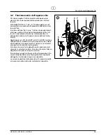
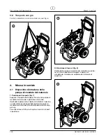
Installazione su un terreno non piano

Il lato anteriore dell'apparecchio deve essere rivolto ver-
so il basso per evitare che l'apparecchio scivoli via.

Norme di sicurezza

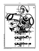
Panoramica sull’impiego

2. Panoramica sull'impiego

2.1

Campi di applicazione

Applicazione di primer e di ultima mano di superfici di
grandi dimensioni, sigillatura, impregnamento, risana-
mento di edifici, protezione e rinnovamento di facciate,
protezione antiruggine e di strutture, rivestimento di tetti,
sigillatura di tetti, risanamento di calcestruzzo e protezio-
ne anticorrosione pesante.

Esempi di oggetti che possono essere trattati

Grandi cantieri, costruzioni sotto il livello del suolo, torri
di raffreddamento, ponti, impianti di depurazione e tet-
toie piane.

Per ragioni di funzionalità, sicurezza e durata
dell'apparecchio occorre utilizzare esclusiva-
mente tubi flessibili ad alta pressione origina-
le WAGNER.

Summary of Contents for HC 35 E

Page 1: ...er l uso p 90 Airless Hochdruck Spritzger t Airless high pressure spraying unit Groupe de projection haute pression Impianto per la verniciatura a spruzzo ad alta pressione Airless HC 35 E HC 45 E HC...

Page 2: ...de Punkte zu beachten 1 Fehlerhafte Ger te d rfen nicht benutzt werden 2 Wagner Spritzpistole sichern mit Sicherungshebel am Abzugsb gel 3 Erdung sicherstellen Der Anschluss muss ber eine vor schrifts...

Page 3: ...Allgemeine Wartung 18 10 2 lstandkontrolle im Hydraulik ltank 18 19 10 3 l und lfilterwechsel bei der Hydraulik lpumpe 19 10 4 Hochdruckschlauch 19 11 Standardausr stung HC Ger te 20 12 Zubeh r und E...

Page 4: ...Bei Airless Spritzpistolen auftretende hohe Spritzdr cke k nnen sehr gef hrliche Verletzungen verursachen Bei Kontakt mit dem Spritzstrahl kann Beschichtungsstoff in die Haut injiziert werden Be hande...

Page 5: ...ng zur Abf hrung der L semitteld mpfe zu gew hrleisten Absaugeinrichtungen Diese sind entsprechend lokaler Vorschriften vom Ger te Benutzer zu erstellen Erdung des Spritzobjekts Das zu beschichtende S...

Page 6: ...nach Herstellerangabe zu verd nnen Zweikomponenten Beschichtungsstoff Die entsprechende Verarbeitungszeit ist genau einzuhal ten Innerhalb dieser Zeit das Ger t sorgf ltig mit dem entsprechenden Rein...

Page 7: ...en HC 45 E SSP und HC 55 E SSP bewegt der Kolben in der Materialf rderpumpe einen Sch pfkol ben 6 Der Sch pfkolben f rdert h chstviskose Beschichtungsstoffe Durch die Aufw rtsbewegung des Kolbens ffne...

Page 8: ...5 E 6 HC 35 E HC 45 E HC 55 E d Ger tebeschreibung 3 3 Legende zum Erkl rungsbild HC Ger te 15 Materialf rderpumpe HC 45 E SSP HC 55 E SSP 16 Materialf rderpumpe HC 35 E 17 Manometer 18 Arretierstift...

Page 9: ...HC 35 E HC 45 E HC 55 E 7 d Ger tebeschreibung 13 20 2 3 4 9 12 17 18 23 24 25 10 14 6 7 1 11 26 21 19 22 20 12 15 19 22 20 12 16 19 22 8 5 3 4 Erkl rungsbild HC Ger te...

Page 10: ...offs 43 C max Viskosit t 40 000 mPa s 50 000 mPa s 65 000 mPa s Filtereinsatz Standardausf hrung 5 Maschen 0 Maschen Gewicht 83 kg 84 5 kg 100 kg 103 kg Hydraulik l F llmenge 4 7 l ESSO Nuto H 32 max...

Page 11: ...E HC 45 E HC 55 E 9 d Ger tebeschreibung 1 2 2 1 2 3 3 7 Transport im Fahrzeug Arretierstift Abb 5 Pos 1 ziehen in der Schwenkein richtung 2 f r die Materialf rderpumpe 3 und diese in waagrechte Lage...

Page 12: ...sport vom Ger t nur in horizontaler Position der Materialf rderpumpe vornehmen Materialf rderpumpe in horizontale Position schwenken erm glicht auch die Materialf rderpumpe aus dem Be schichtungsstoff...

Page 13: ...HC 55 E 11 d Inbetriebnahme 4 2 Position der Materialf rderpumpe ndern 1 Handgriff Abb 10 Pos 1 mit der einen Hand greifen 2 Mit der anderen Hand den Arretierstift 2 ziehen 3 Materialf rderpumpe je na...

Page 14: ...be muss dem Pfeil 4 auf der Riemenabdeckung entsprechen Falls die Riemenscheibe entgegen der Pfeilrichtung l uft Achtung 12 HC 35 E HC 45 E HC 55 E d Inbetriebnahme 6 7 Trenn l einf llen Abb 12 Nur so...

Page 15: ...den Polwender 5 im Netzstecker um 180 Grad drehen Netzstecker wieder einstecken 5 Kugelhahn 6 an der Materialf rderpumpe Hebel senkrecht stellen Hydraulikmotor einschalten Hydraulik l flie t zum Hydr...

Page 16: ...mmpunkt ber 21 C muss dem Beschich tungsstoffe entsprechen Spritzpistole sichern siehe Betriebsanleitung der Spritzpistole D se reinigen und demontieren Standardd se siehe Seite 27 Punkt 13 2 Ist eine...

Page 17: ...m Geh usedeckel 1 abziehen L nge der Druckfeder messen falls weniger als 19 mm dann Druckfeder austauschen Montage 1 Ventilsitz 7 mit der Kugelsitzfl che nach oben in das Geh use 8 einlegen HC 35 E HC...

Page 18: ...St rungen 9 Hilfe bei St rungen 9 1 Elektromotor Ger t l uft nicht an HC 55 E HC 55 E SSP 400 V Kolbenstange in der Mate rialf rderpumpe l uft nicht auf und ab Kontrollleuchte zeigt keine Betriebsbere...

Page 19: ...d im Hydrauliktank Kugelhahn an der Materialf rderpumpe Hebelstel lung senkrecht Verschlussschraube am Hydraulikmo tor oben abschrauben Umschaltventil im Hydraulik motor nach unten dr cken Verschlusss...

Page 20: ...igkeitsspiegel hinaus und saugt Luft an Beschichtungsstoff hat zu hohe Viskosit t um ange saugt zu werden Kugel im Einlassventil geh use klebt fest Lose Verbindungen Entlastungsventil ist nicht ganz g...

Page 21: ...ssen 6 Verschlussschraube wieder einschrauben Umweltgef hrdung Alt l nicht in das Kanalnetz oder Erdreich ab lassen Grundwasserverschmutzung ist straf bar Alt l wird beim Kauf von Hydraulik l zur ckge...

Page 22: ...02 Spritzpistole G 15 2 1088 001 1088 001 1088 001 1088 001 1088 001 Wagner Tip Halter 3 1088 427 1088 427 Wagner Tip D se 0 69 mm 027 40 1088 433 1088 433 1088 433 Wagner Tip D se 0 83 mm 033 40 1088...

Page 23: ...010 0345 010 Inline Roller IR 100 7 0349 907 0349 907 0349 907 0349 907 Container Ansaugsystem Schlauchdurchmesser 50 mm 0349 908 0349 908 Container Ansaugsystem Schlauchdurchmesser 75 mm f r Airless...

Page 24: ...349 597 0349 418 Kugelf hrung 19 0349 419 0349 477 Kugel 20 0349 621 0349 420 Einlassventilgeh use 21 0349 300 0349 300 Ansaugrohr 0349 714 0349 714 0349 701 0349 701 Service Set Materialf rderpumpe 0...

Page 25: ...705 Filterpatrone 100 Maschen Zubeh r 4 0349 432 0349 432 0349 432 Dichtung dick 5 0349 433 0349 433 0349 433 Dichtung d nn 6 0349 434 0349 434 0349 434 O Ring 7 0349 435 0349 435 0349 435 Ventilsitz...

Page 26: ...349 349 0349 349 Schraube 2 19 0349 350 0349 350 Dichtung 20 0349 374 0349 374 Klemm Mutter 23 0349 351 0349 351 Doppelnippel 24 0349 352 0349 352 Winkel 25 0349 353 0349 353 Filter 26 0349 458 0349 4...

Page 27: ...men 6 9921 601 9921 601 Federring 8 4 9921 507 Federring A 10 4 7 3138 808 3138 808 Scheibe 8 4 8 9920 201 Scheibe 10 5 8 8 9910 107 9910 107 Sechskantmutter M 8 4 9910 105 Sechskantmutter M 10 4 9 03...

Page 28: ...17 0349 571 0349 571 Buchse 18 0349 575 0349 575 Distanzh lse 19 3090 520 3090 520 Spannh lse 8 x 28 20 9900 716 9900 716 Zylinderschraube M 5 x 6 21 9922 111 9922 111 Zahnscheibe J 5 3 22 9920 202 99...

Page 29: ...skosit t des Beschichtungs stoffes zu hoch Abhilfe Druck erh hen oder Beschichtungsstoff verd nnen Jede Pumpe leistet eine bestimmte F rdermenge im Verh ltnis zur D sengr e Es gilt grunds tzlich Gro e...

Page 30: ...0 48 320 0090 719 1088 719 1006 719 819 80 0 019 0 48 400 0090 819 1088 819 1006 819 Glimmerfarben 221 20 0 021 0 53 145 0090 221 1088 221 1006 221 Zinkstaubfarben 421 40 0 021 0 53 190 0090 421 1088...

Page 31: ...Am Schenkberg 20 04349 Leipzig Plau ig Tel 0 34 22 98 14 108 0 Telefax 0 34 22 98 14 108 40 a b x e f g i n s Dresden J Wagner GmbH Service St tzpunkt Dresden Joachim Walther Neuhausener Stra e 5 0954...

Page 32: ...must not be used 2 Secure WAGNER spray gun using the safety catch on the trigger 3 Ensure that the unit is properly earthed The connection must take place through a correctly earthed two pole and ear...

Page 33: ...Checking the oil level in the hydraulic oil tank 48 49 10 3 Oil and oil filter change of the hydraulic oil pump 49 10 4 High pressure hose 49 11 Standard equipment of HC units 50 12 Accessories and s...

Page 34: ...nto the skin Do not treat a spray in jury as a harmless cut In the case of injury to the skin through coating material or solvents consult a doctor for quick and correct treatment Inform the doctor ab...

Page 35: ...or pumped back into a container with a small opening bunghole An explosive gas air mixture can be produced The container must be earthed Cleaning the unit Danger of short circuit through pene trating...

Page 36: ...lean the unit meticulously with the appropriate cleaning agents Coating materials with sharp edged additional materials These have a strong wear and tear effect on valves high pressure hose spray gun...

Page 37: ...ydraulic motor 4 and then moves the piston up and down in the material feed pump 5 With devices HC 45 E SSP and HC 55 E SSP the piston in the material feed pump moves a shovel valve 6 The shovel valve...

Page 38: ...eed pump HC 45 E HC 55 E 15 Material feed pump HC 45 E SSP HC 55 E SSP Description of unit 3 3 Explanatory diagram legend HC units 16 Material feed pump HC 35 E 17 Manometer 18 Retention pin for the s...

Page 39: ...HC 35 E HC 45 E HC 55 E 37 g Description of unit 13 20 2 3 4 9 12 17 18 23 24 25 10 14 6 7 1 11 26 21 19 22 20 12 15 19 22 20 12 16 19 22 8 5 3 4 Explanatory diagram HC units...

Page 40: ...ial 43 C Max Viscosity 40 000 mPa s 50 000 mPa s 65 000 mPa s Filter insert standard equipment 5 Maschen 0 Maschen Weight 83 kg 84 5 kg 100 kg 103 kg Hydraulic oil filling quantity 4 7 l ESSO Nuto H 3...

Page 41: ...and then in sert shaft Description of unit 1 2 2 1 2 3 3 7 Transport in vehicle Pull retention pin fig 5 item 1 in the swivel mechanism 2 for the material feed pump 3 and swivel it to a hori zontal po...

Page 42: ...ort position fig 7 Transport unit only if material feed pump is in a horizon tal position Swiveling the material feed pump to a horizontal position also allows removal of the pump from the coating mat...

Page 43: ...n ken bei Einsatz des Container Ansaugsystems Zubeh r In dieser Position ist Freiraum unter der Materialf rderpumpe Starting operation 4 2 Changing the material feed pump position 1 Grip handle fig 10...

Page 44: ...rotation of the pulley must corre spond to the arrow 4 on the belt cover If the belt is running opposite the direction of the arrow Attention Starting operation 6 7 Fill in separating oil fig 12 Do n...

Page 45: ...spond to the arrow 4 on the belt cover If the belt is running opposite the direction of the arrow Switch unit off O OFF Unplug power plug and turn the polarity changer 5 in the power plug by 180 with...

Page 46: ...for the coating material used Secure the spray gun refer to the operating manual of the spray gun Clean and remove tip For a standard tip refer to page 57 point 13 2 If a non standard tip is installed...

Page 47: ...ng the high pressure filter Clean the filter cartridge regularly A soiled or clogged high pressure filter can cause a poor spray pattern or a clogged tip Dismounting 1 Close ball valve on material fee...

Page 48: ...Remedy in case of faults 9 1 Electric motor Unit does not start HC 55 E HC 55 E SSP 400 V Piston rod in the material feed pump is not moving up and down Control lamp does not indi cate operational rea...

Page 49: ...hydraulic tank is too low Ball valve on the material feed pump lever position vertical Screw out sealing screw on hydraulic motor Press down reversing valve on hydraulic motor Remo unt sealing screw S...

Page 50: ...own ward Suction tube projects over the fluid level and sucks in air Coating material viscosity is too high preventing it from being sucked up Ball in inlet valve housing is stuck Loose connections Re...

Page 51: ...the waste oil 6 Remount sealing screw Danger to the environment Do not let waste oil off into the sewage or soil Polluting the ground water is a crime Waste oil can be returned when hydraulic oil is...

Page 52: ...088 001 1088 001 1088 001 1088 001 1088 001 Wagner tip holder 3 1088 427 1088 427 Wagner tip 0 69 mm 027 40 1088 433 1088 433 1088 433 Wagner tip 0 83 mm 033 40 1088 243 1088 243 Wagner tip 1 10 mm 04...

Page 53: ...010 In line roller IR 100 7 0349 907 0349 907 0349 907 0349 907 Container suction system hose diameter 50 mm 0349 908 0349 908 Container suction system hose diameter 75 mm for Airless spray primer 8...

Page 54: ...597 0349 418 Ball guide 19 0349 419 0349 477 Ball 20 0349 621 0349 420 Inlet valve housing 21 0349 300 0349 300 Suction tube 0349 714 0349 714 0349 701 0349 701 Service set material feed pump 0349 71...

Page 55: ...s 0349 705 0349 705 0349 705 Filter cartridge 100 meshes accessories 4 0349 432 0349 432 0349 432 Seal thick 5 0349 433 0349 433 0349 433 Seal thin 6 0349 434 0349 434 0349 434 O ring 7 0349 435 0349...

Page 56: ...sher 2 18 0349 349 0349 349 Screw 2 19 0349 350 0349 350 Seal 20 0349 374 0349 374 Tightening nut 23 0349 351 0349 351 Double nipple 24 0349 352 0349 352 Angle 25 0349 353 0349 353 Filter 26 0349 458...

Page 57: ...0349 587 0349 590 0349 538 Belt 6 9921 601 9921 601 Spring washer 8 4 9921 507 Spring washer A 10 4 7 3138 808 3138 808 Washer 8 4 8 9920 201 Washer 10 5 8 8 9910 107 9910 107 Hexagon nut M 8 4 9910...

Page 58: ...0349 575 0349 575 Distance sleeve 19 3090 520 3090 520 Clamping sleeve 20 9900 716 9900 716 Cylindrical screw M 5 x 6 21 9922 111 9922 111 Lock washer internal teeth J 5 3 22 9920 202 9920 202 Washer...

Page 59: ...too low or the viscosity of the coating material to high Remedy Increase pressure or dilute coating material Each pump conveys a certain quantity in proportion to the size of the tip The following pri...

Page 60: ...320 0090 719 1088 719 1006 719 819 80 0 019 0 48 400 0090 819 1088 819 1006 819 Mica paints 221 20 0 021 0 53 145 0090 221 1088 221 1006 221 Zinc dust paints 421 40 0 021 0 53 190 0090 421 1088 421 1...

Page 61: ...1 Fax 43430528 A B Wagner Spraytech Iberica S A Apartado 132 08750 Molins de Rey Barcelona Spain Phone 93 6800028 Fax 93 6800555 J Wagner France S A R L B P 75 91122 Palaiseau Cedex France Phone 01 60...

Page 62: ...mise en service respecter les points suivants con form ment aux instructions de service 1 Ne jamais utiliser un quipement d fectueux 2 Verrouiller le pistolet Wagner par le levier de s curit la g che...

Page 63: ...8 79 10 3 Vidange d huile et changement du filtre de la pompe hydraulique 79 10 4 Flexible haute pression 79 11 Equipement standard groupes HC 80 12 Accessoires et pi ces de rechange 80 12 1 Accessoir...

Page 64: ...s retard un m decin Renseignez le m decin sur la na ture de la peinture ou du solvant utilis s Danger Danger Danger Verrouiller le pistolet pour viter toute action impr vue Lors du montage ou d montag...

Page 65: ...yant qu une seule petite ouver ture Danger de formation d un m lange gaz air explosif Le r cipient doit tre mis la terre Nettoyage du mat riel Danger de court circuit par la p n tration d eau Ne jamai...

Page 66: ...pecter scrupuleusement le temps d utilisation corre spondant vie en pot Rincer et nettoyer le mat riel l int rieur de ce temps avec le produit de nettoyage ad quat Produits charges abrasives Ces produ...

Page 67: ...huile hydraulique arrive au moteur hydraulique 4 et imprime au piston de la pompe de produit 5 un mouvement de mont e et de descente En ce qui concerne le mat riel HC 45 E SSP et HC 55 E SSP le piston...

Page 68: ...sion 14 Pompe produit HC 45 E HC 55 E Description du mat rial 3 3 L gende de l illustration groupes HCExplanatory diagram legend HC units 15 Pompe produit HC 45 E SSP HC 55 E SSP 16 Pompe produit HC 3...

Page 69: ...HC 35 E HC 45 E HC 55 E 67 f Description du mat rial 13 20 2 3 4 9 12 17 18 23 24 25 10 14 6 7 1 11 26 21 19 22 20 12 15 19 22 20 12 16 19 22 8 5 3 4 Illustration groupes HC...

Page 70: ...ale du produit 43 C Viscosit maximale 40 000 m Pa s 50 000 m Pa s 65 000 m Pa s Cartouche filtrante quipement standard 5 mailles 0 mailles Poids 83 kg 84 5 kg 100 kg 103 kg Capacit d huile hydraulique...

Page 71: ...n du mat rial 1 2 2 1 2 3 3 7 Transport dans un v hicule Retirer le goujon d arr t fig 5 pos 1 dans le dispositif de pivotement 2 de la pompe de produit 3 et pivoter cette derni re en position horizon...

Page 72: ...a pompe de produit 1 Position de transport fig 7 Pendant le transport du groupe la pompe de produit doit tre tourn e en position horizontale Pivoter la pompe de produit en position horizontale pour la...

Page 73: ...de produit Mise en service 4 2 Changement de position de la pompe de produit 1 Saisir la poign e fig 10 pos 1 avec une main 2 Avec l autre main tirer la goupille d arr t 2 3 Pivoter la pompe de produi...

Page 74: ...E HC 55 E HC 55 E SSP Tourner le bouton d interrupteur d abord sur Y ensui te sur MARCHE Attention Mise en service 6 7 Remplir l huile de balayage fig 12 Eviter le trop plein qui pourrait s couler dan...

Page 75: ...E Le sens de rotation de la poulie doit correspondre au sens de la fl che 4 sur la protection de courroie Si la poulie tourne contrairement au sens de fl che Arr ter le groupe O ARRET Tirer la fiche d...

Page 76: ...pe est mont e voir la notice y relative 1 Tirer la goupille d arr t et pivoter la pompe de produit pour la sortir du produit 2 Tirer la g chette du pistolet pour pomper le reste de produit contenu dan...

Page 77: ...ement la cartouche filtrante Un filtre haute pression sale ou bouch occasionne une projection irr guli re ou le bouchage de la buse D montage 1 Fermer la vanne bille de la pompe de produit levier en p...

Page 78: ...mise hors service D pannage 9 D pannage 9 1 Moteur lectrique Le groupe ne d marre pas HC 55 E HC 55 E SSP 400 V La tige de piston de la pompe de produit ne bouge pas La lampe de contr le reste teinte...

Page 79: ...que la pompe de produit aspire de l air Pression faible Garniture de piston du moteur Faire r parer par le S A V Wagner La tige de piston descend hydraulique d fectueuse normalement mais remonte p nib...

Page 80: ...la pompe de produit Tourner le bouton de la vanne de d charge gauche k circulation Bille dans le corps de la D monter le corps de la soupape d aspiration Nettoyer les soupape d aspiration coll e bill...

Page 81: ...hon 10 3 Vidange d huile et changement du filtre de la pompe hydraulique Effectuer la vidange et le changement du filtre tous les 12 mois Danger Arr ter le groupe A ARRET Tirer la fiche de la prise de...

Page 82: ...002 0347 002 0347 002 Pistolet G 15 2 1088 001 1088 001 1088 001 1088 001 1088 001 Porte buse Wagner Tip 3 1088 427 1088 427 Buse Wagner Tip 0 69 mm 027 40 1088 433 1088 433 1088 433 Buse Wagner Tip...

Page 83: ...interne IR 100 7 0349 907 0349 907 0349 907 0349 907 Syst me d aspiration pour conteneurs diam tre du flexible 50 mm 0349 908 0349 908 Syst me d aspiration pour conteneurs diam tre du flexible 75 mm p...

Page 84: ...lle 20 0349 621 0349 420 Corps de la soupape d aspiration 21 0349 300 0349 300 Tube d aspiration 0349 714 0349 714 0349 701 0349 701 Kit de service pompe de produit 0349 715 0349 715 0349 702 0349 702...

Page 85: ...349 705 0349 705 Cartouche de filtre 100 mailles accessoire 4 0349 432 0349 432 0349 432 Joint pais 5 0349 433 0349 433 0349 433 Joint mince 6 0349 434 0349 434 0349 434 Joint torique 7 0349 435 0349...

Page 86: ...8 0349 349 0349 349 Vis 2 19 0349 350 0349 350 Joint 20 0349 374 0349 374 Ecrou de serrage 23 0349 351 0349 351 Raccord double 24 0349 352 0349 352 Coude 25 0349 353 0349 353 Filtre 26 0349 458 0349 4...

Page 87: ...8 Courroie 6 9921 601 9921 601 Rondelle ressort 8 4 9921 507 Rondelle ressort A 10 4 7 3138 808 3138 808 Rondelle 8 4 8 9920 201 Rondelle 10 5 8 8 9910 107 9910 107 Ecrou hexagonal M 8 4 9910 105 Ecro...

Page 88: ...t 17 0349 571 0349 571 Douille 18 0349 575 0349 575 Douille d espacement 19 3090 520 3090 520 Goupille de serrage 8 x 28 20 9900 716 9900 716 Vis cylindrique M 5 x 6 21 9922 111 9922 111 Rondelle dent...

Page 89: ...st trop lev e Rem de Augmenter la pression ou diluer le produit Chaque pompe a un d bit d termin par rapport la grandeur de l orifice de buse R gle g n rale grande buse faible pression petite buse hau...

Page 90: ...20 0090 719 1088 719 1006 719 819 80 0 019 0 48 400 0090 819 1088 819 1006 819 Peintures au mica 221 20 0 021 0 53 145 0090 221 1088 221 1006 221 peintures base de zinc 421 40 0 021 0 53 190 0090 421...

Page 91: ...7 57 22 11 Fax 071 7 57 22 22 Suisse Wagner Spraytech Corp P O Box 9362 Minneapolis 55440 USA T l 612 553 7000 Fax 612 553 7288 USA Wagner Spraytech Japan Ltd 2 35 Shinden Nishimachi Osaka Japon T l 7...

Page 92: ...leva che si trova vicino alla staffa a grilletto 3 Assicurarsi del collegamento alla messa a terra La presa di corrente deve essere munita di un contatto di protezione per la messa a terra in conform...

Page 93: ...gina 10 Manutenzione 108 10 1 Manutenzione generale 108 10 2 Controllo del livello dell olio nel serbatoio dell olio idraulico 108 109 10 3 Cambio dell olio e del filtro della pompa dell olio idraulic...

Page 94: ...diatamente un medico per una rapida e com petente medicazione Informare il medico sul tipo di sostanza impiegata o sul tipo di solvente utilizzato Inserire la sicura dell aerografo per evitare un azio...

Page 95: ...alla formazione di una miscela esplosi va gas aria Il recipiente deve essere collegato a terra Pulizia dell apparecchio Pericolo di cortocircuito dovuto alla pene trazione di acqua Non pulire mai l a...

Page 96: ...deter gente adatto Materiali di copertura con pigmenti a spigoli taglienti Tali materiali esercitano una forte azione abrasiva su val vole tubo flessibile ad alta pressione aerografo e ugello riducen...

Page 97: ...azionando il pistone nella pompa di mandata del mate riale 5 Negli apparecchi HC 45 E SSP e HC 55 E SSP il pistone nella pompa di mandata del materiale azione una valvola di mandata 6 la quale aliment...

Page 98: ...ata del materiale HC 45 E SSP HC 55 E SSP Descrizione dell apparecchio 3 3 Leggenda della figura illustrativa apparecchi HC 16 Pompa di mandata del materiale HC 35 E 17 Manometro 18 Spina di arresto i...

Page 99: ...HC 35 E HC 45 E HC 55 E 97 i Descrizione dell apparecchio 13 20 2 3 4 9 12 17 18 23 24 25 10 14 6 7 1 11 26 21 19 22 20 12 15 19 22 20 12 16 19 22 8 5 3 4 Figura illustrativa apparecchi HC...

Page 100: ...65 000 mPa s Cartuccia filtrante equipaggiamento standard 5 maglie 0 maglie Peso 83 kg 84 5 kg 100 kg 103 kg Quantit necessaria di olio idraulico 4 7 l ESSO Nuto H 32 Pressione dei pneumatici max 2 b...

Page 101: ...recchio 1 2 2 1 2 3 3 7 Trasporto con un veicolo Estrarre la spina di arresto fig 5 pos 1 nel dispositivo di rotozione 2 per la pompa di mandata del materiale 3 e portare quest ultima in posizione ori...

Page 102: ...hio solo con pompa di mandata del materiale in posizione orizzontale Ruotando la pompa di mandata del materiale in posizio ne orizzontale anche possibile togliere la pompa di mandata del materiale dal...

Page 103: ...sa in servizio 4 2 Modifica della posizione della pompa di mandata del materiale 1 Con una mano afferrare l impugnatura fig 10 pos 1 2 Con l altra mano tirare la spina di arresto 2 3 Ruotare la pompa...

Page 104: ...bile 4 a secon da del modello 5 Serrare a fondo il dado a risvolto sul tubo flessibile ad alta pressione e a seconda del modello anche sulla frusta a tubo flessibile per impedire la fuoriuscita del ma...

Page 105: ...arter Se la puleggia ruota in verso opposto a quello della freccia Spegnere l apparecchio O OFF Estrarre la spina di rete e con un cacciavite ruotare di 180 il commuta tore dei poli 5 nella spina di r...

Page 106: ...pirazione nel tubo flessibile ad alta pressio ne e nell aerografo 7 Interruzione del lavoro 1 Chiudere il rubinetto sulla pompa di mandata del ma teriale leva in posizione orizzontale Il flusso di oli...

Page 107: ...rtuccia filtrante Un filtro ad alta pressione sporco o ostruito causa una cattiva figura di spruzzatura o l ostruzione dell ugello Smontaggio 1 Chiudere il rubinetto sulla pompa di mandata del ma teri...

Page 108: ...rless Lavare l aerografo Airless con un detergente adatto a bassa pressione di esercizio Pulire accuratamente l ugello con un detergen te adatto assicurandosi di eliminare tutti i resi dui di material...

Page 109: ...o Raccordi allentati del tubo flessibile dell olio idraulico Livello dell olio insufficiente nel serbatoio idraulico Rubinetto sulla pompa di mandata del materiale leva in posizione verticale Svitare...

Page 110: ...viscosit del materiale di copertura eccessiva per poter essere aspirato La sfera si inceppata nel corpo della valvola di ent rata Raccordi allentati La valvola di sfiato non completamente chiusa La va...

Page 111: ...apparecchio A OFF Disinserire la spina di rete della presa di corrente 10 3 Cambio dell olio e del filtro della pompa dell olio idraulico Eseguire il cambio dell olio e del filtro dell olio ogni 12 m...

Page 112: ...88 001 1088 001 1088 001 1088 001 Supporto Tip Wagner 3 1088 427 1088 427 Ugello Tip Wagner 0 69 mm 027 40 1088 433 1088 433 1088 433 Ugello Tip Wagner 0 83 mm 033 40 1088 243 1088 243 Ugello Tip Wagn...

Page 113: ...ne IR 100 7 0349 907 0349 907 0349 907 0349 907 Sistema di aspirazione a contenitore diametro del tubo flessibile 50 mm 0349 908 0349 908 Sistema di aspirazione a contenitore diametro del tubo flessib...

Page 114: ...19 0349 477 Sfera 20 0349 621 0349 420 Sede della valvola di entrata 21 0349 300 0349 300 Tubo di aspirazione 0349 714 0349 714 0349 701 0349 701 Set di servizio pompa di mandata del materiale 0349 71...

Page 115: ...uccia filtrante 100 maglie accessorio 4 0349 432 0349 432 0349 432 Guarnizione spessa 5 0349 433 0349 433 0349 433 Guarnizione sottile 6 0349 434 0349 434 0349 434 O ring 7 0349 435 0349 435 0349 435...

Page 116: ...0349 349 0349 349 Vite 2 19 0349 350 0349 350 Guarnizione 20 0349 374 0349 374 Dado di arresto 23 0349 351 0349 351 Nipplo doppio 24 0349 352 0349 352 Squadretta 25 0349 353 0349 353 Filtro 26 0349 45...

Page 117: ...oidale 6 9921 601 9921 601 Anello elastico 8 4 9921 507 Anello elastico A 10 4 7 3138 808 3138 808 Rondella 8 4 8 9920 201 Rondella 10 5 8 8 9910 107 9910 107 Dado esagonale M 8 4 9910 105 Dado esagon...

Page 118: ...a tubo 19 3090 520 3090 520 Bussola di serraggio 8 x 28 20 9900 716 9900 716 Vite a testa cilindrica M 5 x 6 21 9922 111 9922 111 Rosetta elastica dentata J 5 3 22 9920 202 9920 202 Rondella 5 3 23 0...

Page 119: ...oppure la viscosit del materiale di copertura eccessiva Rimedio aumentare la pressione o diluire il materiale di spruzzatura Ogni pompa possiede una determinata portata in rapporto alle dimensioni del...

Page 120: ...1006 719 819 80 0 019 0 48 400 0090 819 1088 819 1006 819 Vernici in mica 221 20 0 021 0 53 145 0090 221 1088 221 1006 221 Vernici a polvere di zinco 421 40 0 021 0 53 190 0090 421 1088 421 1006 421...

Page 121: ...Via Magnadola 28 31045 Motta di Livenza TV Tel 0422 861126 Fax 0422 861128 TORINO Filiale Via Volpiano 64 10040 Lein TO Tel 011 9974431 Fax 011 9973376 AREZZO Filiale Via Da Vinci 2 52029 Castiglion...

Page 122: ...HC 45 E HC 55 E d Zubeh rbild g Accessories illustration f Illustration des accessoires i Figura degli accessori MAX 250BAR 3600PSI 8 9 5 4 1 6 3 2 7 7 10 HC 35 E HC 45 E HC 45 E SSP HC 55 E HC 55 E S...

Page 123: ...Figura dei ricambi d Materialf rderpumpe f Pompe de produit g Material feed pump i Pompa di mandata del materiale HC 35 E 15 1 2 6 7 4 3 2 5 1 8 13 6 16 22 15 11 14 9 10 17 23 18 19 21 HC 35 11 02 HC...

Page 124: ...E HC 55 E Ersatzteilbild Spare parts diagram Illustration des pi ces de rechange Figura dei ricambi d Sch pfkolben f Piston auget g Shovel valve i Valvola di mandata 14 4 5 1 6 7 2 9 11 13 12 21 28 30...

Page 125: ...ts diagram Illustration des pi ces de rechange Figura dei ricambi d Hochdruckfilter f Filtre haute pression g High pressure filter i Filtro ad alta pressione HC 35 E HC 45 E HC 45 E SSP HC 55 E HC 55...

Page 126: ...de rechange Figura dei ricambi d Hydrauliksystem f Syst me hydraulique g Hydraulic system i Sistema idraulico HC 35 E HC 45 E HC 45 E SSP HC 55 E HC 55 E SSP 27 27 31 30 1 13 26 2 4 43 5 6 3 8 7 9 10...

Page 127: ...s pi ces de rechange Figura dei ricambi d Antrieb mit Elektromotor f Entra nement avec moteur lectrique g Systems with an electric motor i Sistema di azionamento con motore elettrico HC 35 E HC 45 E H...

Page 128: ...s diagram Illustration des pi ces de rechange Figura dei ricambi d Wagen f Chariot g Carriage i Carrello HC 35 E HC 45 E HC 45 E SSP HC 55 E HC 55 E SSP 13 4 15 3 4 5 7 6 8 9 25 24 27 26 28 29 37 39 3...

Page 129: ...oder uns schriftlich mitzuteilen Wir behalten uns vor die Garantie durch ein Vertragsunternehmen er f llen zu lassen Die Leistung dieser Garantie ist abh ngig vom Nachweis durch Rech nung oder Liefers...

Page 130: ...une restriction des revendications l gales ou contractuelles d finies par nos conditions g n rales de vente J Wagner GmbH Sous r serve de modification Imprim en R F A Avvertenza importante sulla respo...

Page 131: ...25 Date 17 06 2002 g i Declaration of conformity Herewith we declare that the supplied version of WAGNER HC 35 E HC 45 E HC 45 E SSP HC 55 E HC 55 E SSP Complies with the following provisons applying...

Reviews: