background image

VC

PC

TV

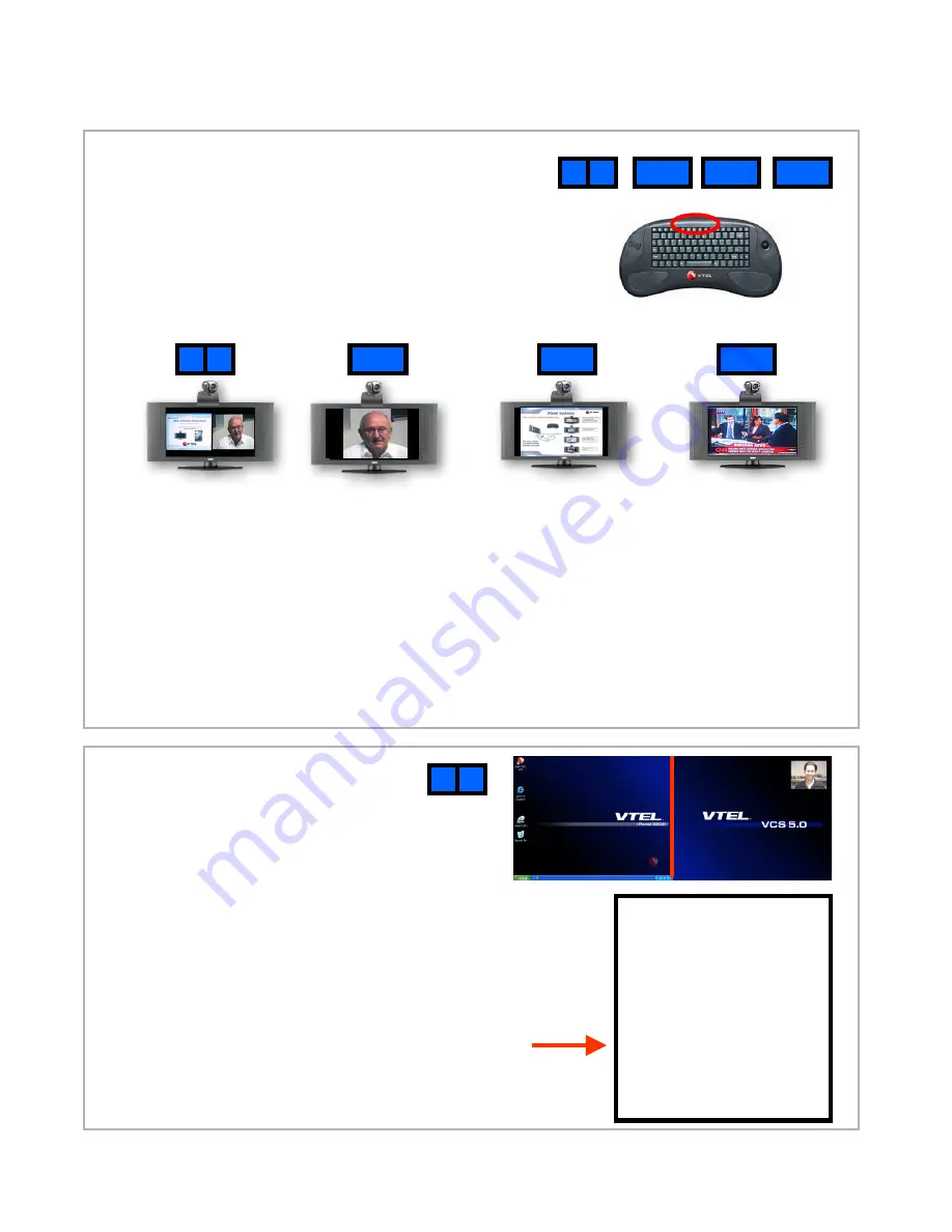
PC  VC

F6          F7         F8         F9

4. System modes

The IPanel has four main modes of operation. 
You can toggle from one mode to another with one
button push using the four function keys highlighted
to the right.  

Note: these speed function keys only

operate when the VTEL VCS software is running
(see step 3.D and 3.E).

VC

PC

TV

PC  VC

Videoconferencing

Normal operation 
for videoconference-
PC information on 
left,  video on right

Videoconferencing

Select VC to see full
screen of far site in
videoconference

Videoconferencing 

or

Local PC 

Presentation

Select PC to see full
screen of received PC
data in videoconference.
Select PC to see full size
presentation locally when 
not in a videoconference

TV viewing

Select TV to see full
screen of cable TV 
programs (includes
HDTV tuner)

5. Videoconferencing

Notes: (1) changing modes may take about
10 seconds.  The flat panel is going through
a series of commands to set up the correct
display. (2) for PC or VC modes, if you can’t
see mouse cursor roll it over to left or right.

Note: The keyboard mouse works normally as a 
PC mouse when the cursor is in the PC area…
and the keyboard mouse works as a videoconferencing 
controller when the cursor is in the videoconferencing area.

B.  Move the cursor to the right hand section (it will turn blue)
C.  Right-click and the videoconferencing menu appears:

PC  VC

A.  Assuming you are starting from step 3E,

press PC/VC button (F6) 

The screen at right will appear.

The left half is your local PC.
The right half is the videoconferencing section.

Place a Call
Audio Mute
Video Mute
Volume Control
Local Video
My IP Address
Exit VTEL Now
Cancel

Summary of Contents for IPanel 2600

Page 1: ...VTEL IPanel VCS 5 0 User Guide IPanel 2600 IPanel 3200 IPanel 4200 IPanel 3700 ...

Page 2: ...t to over tighten the screws Align the camera bracket with the front of the monitor and stick it down with the double sided tape B Using a Philips screwdriver remove the large silver screw from the bottom of the camera and use it to mount the camera mounting plate to the camera Be careful not to over tighten the screw Note The L shaped part of the mounting plate containing two small holes should f...

Page 3: ... on the lower right front or lower right under the edge of the panel B The system will start up like any other Windows XP computer going through familiar screens C This computer screen will fill the panel s display 3 Starting up the system D Double click on the red V ball Start VTEL VCS shortcut in the upper left corner This launches the videoconferencing software E After a brief loading process a...

Page 4: ...elect TV to see full screen of cable TV programs includes HDTV tuner 5 Videoconferencing Notes 1 changing modes may take about 10 seconds The flat panel is going through a series of commands to set up the correct display 2 for PC or VC modes if you can t see mouse cursor roll it over to left or right Note The keyboard mouse works normally as a PC mouse when the cursor is in the PC area and the key...

Page 5: ...izontal entry and drag and dropping it onto a key To add a site Right click in the address book white portion and bring up menu with add at the top This is how to add sites to your address book 5A Videoconferencing Menu Placing a call Managing the address book Place a Call Audio Mute Video Mute Volume Control Local Video My IP Address Exit VTEL Now Cancel Muting On Master Menu click Audio Mute so ...

Page 6: ...t the camera to go Hang Up Address Book Audio Mute Video Mute Volume Control Send PC Local Video My IP Address Cancel Left click on My IP Address This is the number that other people should call to reach this system It s like a phone number The IP address appears on the top of the PC left screen in PC VC mode If you are in VC mode far site video picture only the IP address will not appear 5D Video...

Page 7: ...ny other PC application to the other participants While in PC VC mode like picture at right start your PowerPoint application in the left PC side Maximize the size of the slides locally Right click on the video right side and bring up the videoconferencing menu Select Send PC an ICON appears on your video side In about 10 15 seconds the far site conferencing unit will also see your PowerPoint slid...

Page 8: ...stem The large flat panel display is good for group meetings showing local PowerPoint presentations EXCEL spreadsheets or any other PC based application Use the IPanel just like a VGA projector for the local meeting participants DVD PC screen Press PC button F8 if VTEL VCS 5 0 is running see steps 3D and 3E Insert DVD into DVD drive on IPanel base Double click Power DVD icon on PC desktop VTEL PC ...

Page 9: ...l YES NO NO YES YES NO B A B C 6 IPanel Network Setup for Public Internet The IPanel is designed to videoconference over the public Internet The initial setup may involve your local IT computer network support person to configure your IP network parameters especially your network firewall and some internal IPanel settings This will only have to be done once at initial system installation Thereafte...

Page 10: ...ur IPanel make sure you setup the same network properties for the same port you plug your cable into Facing the back of the iPanel adapter 1 is on the left Local Area Connection and adapter 2 Local Area Connection 2 is on the right It s perfectly ok to set up both adapters with the same information A By default your IPanel is setup to use automatic IP detection DHCP on both of its Ethernet ports I...

Page 11: ... the camera power cable part of umbilical 4 Attach VISCA cable to port labeled VISCA IN camera and other end into upper most COM port COM 2 part of umbilical 5 Attach S Video cable to camera port and the other end into connector on video dongle cable 2 with arrow pointing towards PC 6 Attach one end of this cable to connector on video dongle pointing away from PC and other end to the right most S ...

Page 12: ...n each end of the LCD panel control cable Be sure to use the lower COM port COM 1 on the PC 10 Plug one end of this audio cable into the Y splitter Match the red and white jacks to their left most audio receptacles on LCD 11 Plug one end of this audio cable into the into the Y splitter Match the red and white jacks to their right most audio receptacles on LCD 12 Plug the Y splitter into the green ...

Reviews: