16
Connecting a target chip
●
1
8 MCLR
VCC 2
7 GND
3
6
PGC 4
5 PGD
10Fxxx chips in 8-pin DIP
●
VCC 1
8 GND
2
7 PGD
3
6 PGC
MCLR 4
5
12Fxxx chips in 8-pin DIP
●
VCC 1
14 GND
2
13 PGD
3
12 PGC
MCLR 4
11
5
10
6
9
7
8
14-pin DIP
●
VCC
1
20 GND
2
19 PGD
3
18 PGC
MCLR 4
17
5
16
6
15
7
14
8
13
9
12
10
11
20-pin DIP
●
1
28 MCLR
VCC
2
27
3
26
GND
4
25
5
24
6
23
7
22
8
21
9
20
10
19
11
18
12
17
PGD
13
16
PGC
14
15
28-pin wide DIP
●
MCLR 1
40 PGD
2
39 PGC
3
38 PGM
4
37
5
36 PGM
6
35
7
34
8
33
9
32 VCC
10
31 GND
VCC
11
30
GND 12
29
13
28
14
27
15
26
16
25
17
24
18
23
19
22
20
21
40-pin DIP
(newer PICs)
●
MCLR 1
28 PGD
2
27 PGC
3
26 PGM
4
25
5
24 PGM
6
23
7
22
GND
8
21
9
20 VCC
10
19 GND
11
18
12
17
13
16
14
15
28-pin skinny DIP
●
1
18
2
17
3
16
MCLR 4
15
GND 5
14 VCC
6
13 PGD
7
12 PGC
8
11 PGM
9
10 PGM
18-pin DIP
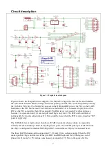
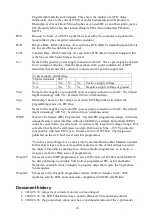
The pictures show how the colored wires of the Wisp648 should be connected to various target
chips. For readability the black wire is shown here as gray, and the white wire (PGM) is shown in a
box on a white background.. Note the difference in pinout between the 10F and 12F series, which
both use an 8-pin package, and between the small and wide 28-pins packages. Also note that, as far
as in-circuit programming is concerned, the 8 pin (12Fxxx only), 14 pin, and 20 pin DIP packages
are sufficiently similar to program these chips in one (20 pin) socket. The PGM pin varies between
chips, check the chips datasheet for the correct pin.


