


10
Place and solder the LED. The longer wire must be put in the hole
in the middle of the silk ‘symbol’ for the LED. In other words:
insert the longer wire in the hole nearest to the DB15 connector.
Trim the wires.
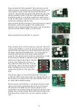
Place and solder the BC550 transistor. The flat side of the transistor
must be as show: towards the resistors.
Place and solder the 20 MHz resonator. Trim the wires.
Place and solder the two-pin header.
The latest version of the PCB uses a three-pin header.
Place and solder the screw connector.
Place and solder the centre-pin power
connector. I find it convenient to bend two
of the pins before soldering.
Place and solder the one 22
µ
F electrolytic capacitor. The longer
wire must be inserted in the hole marked with a +. Or: all
electrolytic capacitors must have their white bands towards the
DB15 connector.
Place and solder the six 1
µ
F electrolytic capacitor. The longer wire
must be inserted in the hole marked with a +. Or: all electrolytic
capacitors must have their white bands towards the DB15
connector.