


14
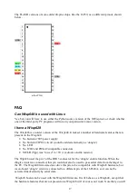
Pin
name
Wisp648 function
1
CD
not used, but connected to 4 and 6
2
RxD
Serial data: Wisp648-to-PC
3
TxD
Serial data: PC-to-Wisp648
4
DTR
not used, but connected to 1 and 6
5
GND
Ground
6
DSR
not used, but connected to 1 and 4
7
RTS
not used, but connected to 8
8
CTS
not used, but connected to 7
9
RTI
Not used
DB15 male: connection to target
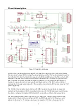
The colors correspond to the colors of the wires supplied with the kit. No wires are supplied for
pins 7 and 8, so no colors are shown for these lines.
Pin
Wisp648 function
1
Ground
2
+5V
3
PGC
4
PGD
5
MCLR
6
PGM (LVP)
7
Asynch Wisp648
target
8
Asynch Wisp648
target
9..15
Not used
Black centre-pin connector and screw connector: wall-wart
The Wisp648 has two power connectors; you can use the one you prefer. The black 2.5 mm centre-
pin connector is convenient and matches the connector often found on wall-warts. The screw
connector is more reliable and should be used when a more permanent connection is to be made.
The crew connector is clearly marked ‘0’ and ‘+’. The centre-pin of the black connector must be
positive.
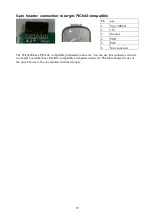
RJ11/12 connector: connection to target, ICD2 compatible
Pin
use
1
Not connected
2
PGC
3
PGD
4
Ground
5
+5V
6
Vpp / MCLR
The RJ11/12 connector is compatible with the connector on a Microchip ICD2. Note that the
Microchip ICD2 cable reverses the pins, so the pin assignment at the target side is the mirror of the
pin assignment at the programmer side. The table shows the pin assignment at the programmer
side.
2 3
4
5
1